| Business DEX (LOGSA007):— reliability_and_failure_mode |
Date: 2010/12/29 16:34:39
Revision: 1.25
|
For the purposes of this specification, the following terms apply:
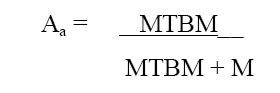
achieved_availability
The probability that, when used under stated conditions in an ideal support environment, a system will operate
satisfactorily at any time. This differs from Inherent Availability only in its inclusion of consideration for preventive
action. Aa excludes supply downtime and administrative downtime. The measurement bases for MTBM and M must be consistent when
calculating Aa.
Aa may be expressed by the following formula:
Figure 1 — Achieved Availability Formula 1
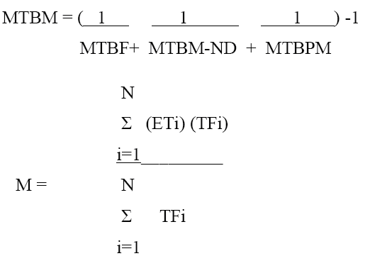
Where
Figure 2 — Achieved Availability Formula 2
MTBM = Mean time between maintenance
MTBF = Mean time between failure
MTBM-ND = Mean time between maintenance no defect
MTBPM = Mean time between preventive maintenance
M = Mean active maintenance downtime (where corrective and preventive actions are considered)
ETi = Elapsed time for task i
TFi = Task frequency for task i
N = Total number of tasks performed
Note: The measurement bases for MTBF, MTBM-ND, and MTBPM must be consistent when calculating the MTBM parameter.
administrative_and_logistics_delay_time
The total time in days the system/equipment is inoperable due to delays in maintenance that are attributable to administration
and logistics.
alternate_logistics_support_analysis_control_number_code (ALC)
A code used to allow documentation of multiple models of a system/equipment, or alternate design considerations of an item,
using the same LCN breakdown.
built_in_test_cannot_duplicate_percentage
The percent of all Built-in-Test (BIT) indicated malfunctions provided during usage of the equipment that cannot be verified
by maintenance personnel performing onequipment troubleshooting.
built_in_test_detectability_level_percentage
A BIT consists of an integral capability of the mission equipment that provides an onboard automated test capability to detect,
diagnose, or isolate system failures. The fault detection/isolation capability is used for momentary or continuous monitoring
of a system's operational health, and for observation/diagnosis as a prelude to maintenance action.
BIT subsystems may be designed as an analysis tool for the overall system, integrated with several subsystems, or may be designed
as an integral part of each removable component. Detectability Level Percentage is the probability that the malfunction or
failure of the UUT will be detected by BIT multiplied by l00.
Detectability Percent = ((Number of BIT dectectable failures) *100) / (Total number of failures)
built_in_test_retest_ok_percent
The percent of items removed from an end item as a result of BIT indicated malfunction that subsequently pass all related
testing at the next maintenance level (e.g., intermediate shop).
conversion_factor
A factor (with a decimal locator code) used to convert the AOR of the system/equipment to the AOR of the item under analysis.
The factor is obtained by dividing the rate of usage of the item under analysis (expressed in cycles, miles, rounds, hours,
or any other appropriate measurement base) by the rate of usage of the system/ equipment (also expressed in the same MB).
end_item_acronym_code (EIAC)
A code that uniquely identifies the system/equipment end item. This code will be assigned by the requiring authority. It will
remain constant throughout the item’s life cycle (e.g., TOW, PATRIOT, Tomahawk, Sparrow, and ALCM).
engineering_failure_mode_mean_time_between_failure
For a particular interval, the total functional life of a population of an item divided by the total number of failures within
the population during the measurement interval. The definition holds for time, rounds, miles, events, or other measure of
life units.
Mean time between failures (MTBF) is documented as both technical and operational characteristics. Technical parameters reflect
the technical reliability that the system/equipment must demonstrate. In determining these parameter values, all failures
and resultant actions to restore the item will be considered (e.g., a broken tail light is a technical, but not operational
characteristic). Operational parameters reflect operational reliability and maintainability characteristics that the system
must demonstrate. Only operational mission failures and the resultant tasks are included (e.g., engine failure will result
in mission abort that is both an operational and technical failure).
failure_cause_narrative
A description of all possible failure causes postulated on the basis of the stated requirements in the system and failure
definitions. All probable independent causes for each failure shall also be identified and described. The failure causes within
adjacent indenture levels shall be considered. For example, failure causes at the third indenture level shall be considered
when conducting a second indenture level analysis.
failure_damage_mode_effect_end_effect_narrative
A description of the consequences of each failure/damage mode end effect on the item operation, function, or status. Failure/damage
effects focus on the specific block diagram element, which is affected by the condition under consideration. End effects evaluate
and define the total effect a failure/damage mode has on the operation, function, or status of the uppermost system. The
effect of each failure/damage mode upon the essential functions(s) affecting system/equipment operating capability and mission
completion capability shall be determined. The end effect described may be the result of a double failure. For example, failure
of a safety device may result in a catastrophic end effect only in the event that both the prime function goes beyond the
limit for which the safety device is set, and the safety device fails.
failure_damage_mode_effect_local_narrative
A description of the consequences of each failure/damage mode effect local on the item operation, function, or status. Failure/damage
effects focus on the specific block diagram element, which is affected by the condition under consideration. Local effects
concentrate specifically on the impact a failure/damage mode has on the operation and function of the item in the indenture
level under consideration. The consequences of each postulated failure/damage mode affecting the item shall be described
along with any second order effects that result. Potential conditions where the failure/damage of one item results in a change
of the conditional failure probability, or effect of a second item shall be identified. It is possible for the "local effect"
to be the failure/damage mode itself.
failure_damage_mode_effect_next_higher_narrative
A description of the consequences of each failure/damage mode effect on the next higher on the item operation, function, or
status. Failure/damage effects focus on the specific block diagram element, which is affected by the condition under consideration.
These effects concentrate on the impact a failure/damage mode has on the operation and function of the items in the next higher
indenture level above the indenture level under consideration. The consequences of each failure/damage mode affecting the
next higher indenture level shall be described.
failure_damage_mode_narrative
A description of all possible failure/damage modes postulated on the basis of the stated requirements in the system and failure
definitions. All probable independent causes for each failure shall also be identified. A description of all possible damage
modes that could result from specific threats.
Failure modes: The manner by which a failure occurs. All predictable failure modes for each indenture level analyzed shall
be identified and described. Potential failure modes shall be determined by examination of item outputs and functional outputs
identified in applicable block diagrams and schematics. Failure modes of the individual item function shall be postulated
on the basis of the stated requirements in the system definition and the failure definitions included in the ground rules
developed to support the Failure Modes, Effects, and Criticality Analysis (FMECA) approach. Where functions shown on a block
diagram are performed by a replaceable module in the system, a separate Failure Modes and Effects Analysis (FMEA) shall be
performed on the internal functions of the module, viewing the module as a system. The effects of possible failure modes in
the module inputs and outputs describe the failure modes of the module when it is viewed as an item within the system. Each
failure mode and output function is examined in relation to the following typical failure conditions:
- Premature operations
- Failure to operate at a prescribed time
- Intermittent operation
- Failure to cease operation at a prescribed time
- Loss of output or failure during operation
- Degraded output or operational capability
- Other unique failure conditions, as applicable, based upon system characteristics and operational requirements or constraints.
Damage Modes: A narrative description identifying all possible damage modes that could result from exposure to specified threat
mechanism(s) determined through analysis of each subsystem, component, or part. The analysis includes both primary and secondary
damage effects. Damage modes of individual item functions are postulated on the basis of the stated mission requirements,
specified threats, and system descriptions. The effects of the possible damage modes include performance degradation, as well
as total item failure. Each damage mode and function is examined in relation to the following typical damage conditions:
- Penetrated
- Severed
- Shattered, cracked
- Jammed
- Deformed
- Ignited, detonated
- Burned out (i.e., electrical overload)
- Burned through (i.e., threat-caused fires)
failure_effect_probability
The values are the conditional probability that the failure effect will result in the assigned (SHSC) Safety Hazard Severity
Code given that the failure mode occurs. The values represent the analyst's judgment as to the conditional probability that
the loss will occur, and are quantified in general accordance with the following:
|
Failure Effect
|
Value
|
|
Actual Loss
|
1.00
|
|
Probable Loss
|
0.10 to 1.00
|
|
Possible Loss
|
0.00 to 0.10
|
|
No Effect
|
Not Applicable
|
Table — Failure Effect Probability
failure_mode_classification
A one-position code that categorizes the failure resulting from the identified failure mode as a technical or an operational
failure.
|
Code
|
Description
|
|
T
|
Technical
|
|
O
|
Operational
|
Table — Failure Effect Probability
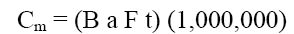
failure_mode_criticality_number
Cm is that portion of the criticality number for an item, which accounts for a specific one of its failure modes under a particular
severity classification. For a particular severity classification and operational phase, the Cm for a failure mode may be
calculated with the following formula:
Figure 8 — Failure Mode Criticality Number Formula
Where:
Cm = Criticality Number for Failure Mode
B = Failure Effect Probability
a = Failure Mode Ratio
F = Part Failure Rate
t = Operating Time
failure_mode_detection_method_narrative
A description of the method(s) by which occurrence of a specific failure mode is detected by the operator or maintenance technician.
It describes warning devices, if applicable, and other indications that make evident to the operator or technician that a
system/equipment has malfunctioned or failed. If no indication exists, states if the undetected failure will jeopardize the
mission objectives or personnel safety, and if the undetected failure allows the system to remain operational in a safe state,
explores possible resulting second failure situations. Proper correlation of a system malfunction or failure may require identification
of normal, as well as abnormal indications. Normal indications are those that are evident to an operator when the system is
operating normally. Abnormal indications are those that are evident to the operator when the system has malfunctioned or failed.
failure_mode_indicator
The first position of the code describes whether the indicator is failure mode (F) or damage mode (D). The next three positions
of the code are alphanumeric, but not special characters. This four-position code links information on an entity to a particular
failure or damage mode.
failure_mode_indicator_mission_characteristics_compensating_design_provisions_narrative
A description of compensating design provisions that circumvent or mitigate the effect of the failure. A record of the true
behavior of the item in the presence of an internal malfunction or failure. Features of the design at any indenture level
that will nullify the effects of a malfunction or failure, control or deactivation system items to halt generation or propagation
of failure effects, or activate backup or standby items or systems. Redesign compensating provisions include: redundant items
that allow continued and safe operation; safety or relief devices such as monitoring or alarm provisions that permit effective
operation or limit damage; or alternate models ofoperation such as backup or standby items or systems.
failure_mode_indicator_mission_characteristics_compensating_operator_action_provisions_narrative
A description of compensating operator action provisions that circumvent or mitigate the effect of the postulated failure.
Describes the compensating provision that best satisfies the indication(s) observed by an operator when the failure occurs,
and the consequences of any probable incorrect action(s) by the operator in response to an abnormal indication.
failure_mode_predictability_narrative
Narrative information on known incipient failure indicators (e.g., operational performance variations), which are peculiar
to the item failure trends and permit predicting failures in advance.
failure_mode_ratio
The fraction of the failure rate of the part, related to the particular failure mode under consideration. The failure mode
ratio is the probability expressed as a decimal fraction that the part or item will fail in the identified mode. If all potential
failure modes of a particular part or item are listed, the sum of the "a" values for the part or item will equal one. Individual
failure mode multipliers may be derived from failure rate source data or from test and operational data. If failure mode data
are not available, the "a" values represent the analyst's judgment based upon an analysis of the item's functions.
failure_mode_redesign_recommendations_narrative
A narrative description identifying recommended design changes, disposition of each recommendation, and the results of each
recommendation for which analysis indicates a redesign might be warranted. It includes appropriate feasibility and cost benefit
analysis results performed to validate the redesign recommendations.
failure_mode_remarks_narrative
A narrative that states a condition not readily identified by other failure mode narrative. This element is related to a failure
mode, therefore, it should preface with a reference to a specific failure mode. This is a narrative clarification of data
pertaining to failure modes.
failure_mode_task_alternate_logistics_support_analysis_control_number_code
A code used to allow documentation of multiple models of a system/equipment, or alternate design considerations of an item,
using the same LCN breakdown.
NOTE:
- ALC of zero,zero “00” will always be used as the basic system. There are no blanks allowed. ALCs will be assigned from 01
to ZZ in ascending order.
- ALC equates to S1000D Disassembly Code Variant, which is a constituent element of the Data Module Code.
failure_mode_task_failure_mode_indicator
See failure_mode_indicator
failure_mode_task_logistics_support_analysis_control_number
A code that represents a functional or hardware generation breakdown/disassembly sequence of system/equipment hardware including
SE, training equipment, and installation (connecting) hardware. For additional information on assignment of LCN, refer to
the GEIA-HB-0007.
failure_mode_task_logistics_support_analysis_control_number_type
failure_probability_level
A single-position code identifying the qualitative level assigned to the failure probability of occurrence. The levels are
as follows:
- Level A - Frequent. A high probability of occurrences during the item operating time interval. High probability may be defined
as a single failure mode probability of occurrence equal to or greater than 0.20 of the overall probability of failure during
the item operating time interval.
- Level B - Reasonably Probable. A moderate probability of occurrence during the item operating time interval. Reasonably probable
may be defined as a single failure mode probability of occurrence that is 0.10 or more, but less than 0.20 of the overall
probability of failure during the item operating time interval.
- Level C - Occasional. An occasional probability of occurrence during item operating time interval. Occasional probability
may be defined as a single failure mode probability of occurrence that is 0.01 or more, but less than 0.10 of the overall
probability of failure during the item operating time.
- Level D - Remote. An unlikely probability of occurrence during item operating time interval. Remote probability may be defined
as a single failure mode probability of occurrence that is 0.001 or more, but less than 0.0l of the overall probability of
failure during the item operating time.
- Level E - Extremely Unlikely. A failure whose probability of occurrence is essentially zero during item operating time interval.
Extremely unlikely may be defined as a single failure mode probability of occurrence, which is less than 0.00l of the overall
probability of failure during the item
failure_rate
For a particular interval, the total number of failures within a population of an item divided by the total functional life
of the population during the measurement interval. The definition holds for time, rounds, miles, events, cycles, or other
measures of life units.
failure_rate_data_source
The source of the failure rates used in the calculation of criticality numbers. Failure rate data can be obtained from sources
such as appropriate reliability predictions, test and evaluation results, field data from past systems of similar design and
environmental use, or failure rate data sources such as MIL-HDBK-217.
fault_isolation_ambiguity_group
Fault Isolation is a procedure employed to determine which particular unit or group of units is at fault for a malfunction
or failure. Specific information related to the BIT capability to fault isolate is provided in the subfields of this block.
Ambiguity Group - a set of items at the same level of indenture having properties such that BIT can determine that at least
one of the set is faulty, but is unable to determine which particular one.
fault_isolation_ambiguity_group_1
See fault_isolation_ambiguity_group
fault_isolation_ambiguity_group_2
See fault_isolation_ambiguity_group
fault_isolation_percent_failure_group
Fault Isolation is a procedure employed to determine which particular unit or group of units is at fault for a malfunction
or failure. Specific information related to the BIT capability to fault isolate is provided in the subfields of this block.
Percent Failure - the percent of an item’s probable malfunctions, which can be isolated within a specific ambiguity group
by means of BIT.
fault_isolation_percent_failure_group_1
See fault_isolation_percent_failure_group
fault_isolation_percent_failure_group_2
See fault_isolation_percent_failure_group
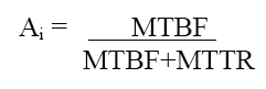
inherent_availability
The probability that, when used under stated conditions in an ideal support environment without consideration for preventive
action, a system will operate satisfactorily at any time. The "ideal support environment" referred to exists when the stipulated
tools, parts, skilled manpower, manuals, SE, and other support items required are available. Ai excludes whatever ready time,
preventive maintenance downtime, supply downtime, and administrative downtime may be required. Ai may be expressed by the
following formula:
Figure 3 — Inherent Availability Formula
Where MTBF = Mean Time Between Failures
MTTR = Mean Time To Repair
NOTE: The measurement bases for MTBF and MTTR must be consistent when calculating Ai.
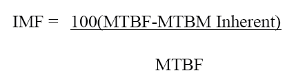
inherent_maintenance_factor
A factor derived from historical information that identifies the percent of No Defect maintenance actions that have been included
in the MTBM Inherent parameter. This factor is used to relate the MTBM Inherent parameter to the MTBF parameter. The IMF may
be calculated using the following formula:
Figure 4 — Inherent Maintenance Factor Formula
Where:
MTBF = Mean Time Between Failures
MTBM Inherent = Mean Time Between Maintenance Inherent
logistics_considerations_accessibility
A logistic consideration indicating whether admission to the various areas of the item under analysis can be achieved with
relative ease.
logistics_considerations_connectors
A logistic consideration indicating whether the item design includes the use of connectors to facilitate removal.
logistics_considerations_corrosion_rust_control
A logistic consideration indicating whether adequate corrective or preventive actions have been developed to deter corrosion
or rust damage to the item under analysis.
logistics_considerations_design_for_self_protection
A logistic consideration indicating whether provisions have been made to restrict the progress of deterioration after failure
of the item under analysis.
logistics_considerations_fault_location
A logistic consideration indicating whether adequate design provisions have been made to facilitate the location of the causes
of failures or malfunctions of the item under analysis.
logistics_considerations_for_accessibility_narrative
A logistic consideration indicating whether admission to the various areas of the item under analysis can be achieved with
relative ease.
logistics_considerations_for_connectors_for_ease_of_removal_narrative
A logistic consideration indicating whether the item design includes the use of connectors to facilitate removal.
logistics_considerations_for_corrosion_and rust_control_narrative
A logistic consideration indicating whether adequate corrective or preventive actions have been developed to deter corrosion
or rust damage to the item under analysis.
logistics_considerations_for_design_for_self_protection_narrative
A logistic consideration indicating whether provisions have been made to restrict the progress of deterioration after failure
of the item under analysis.
logistics_considerations_for_fault location_narrative
A logistic consideration indicating whether adequate design provisions have been made to facilitate the location of the causes
of failures or malfunctions of the item under analysis.
logistics_considerations_for_labeling_narrative
A logistic consideration indicating whether adequate parts associated with maintenance are identified and visible with respect
to circuit symbol or part identification.
logistics_considerations_for_maintenance_ease_narrative
A logistic consideration indicating whether required maintenance can be performed without physical difficulty.
logistics_considerations_for_packaging_and_transportation_narrative
A logistic consideration indicating whether the packaging material and transportation mediums, designed for the item under
analysis, will adequately protect it during transport.
logistics_considerations_for_safety_narrative
A logistic consideration indicating whether adequate design provisions have been made to ensure the conservation of human
life and effectiveness, and the prevention of damage to items, consistent with mission requirements.
logistics_considerations_for_skills_narrative
A logistic consideration indicating whether existing skills are available and sufficient to perform required maintenance on
the item under analysis.
logistics_considerations_for_standardization_narrative
A logistic consideration indicating whether the design of the item under analysis meets the DOD policy to adapt, when possible,
to:
- common or compatible operational, administrative and logistic procedures
- common or compatible technical procedures and criteria
- common, compatible, or interchangeable supplies, components, weapons, or equipment
- common or compatible tactical doctrine with corresponding organizational compatibility
logistics_considerations_for_test_points_narrative
A logistic consideration indicating whether adequate design considerations have been made for test points on the item under
analysis.
logistics_considerations_for_training_narrative
A logistic consideration indicating whether adequate training programs have been planned for the performance of operator/maintainer
tasks on the item under analysis.
logistics_considerations_labeling
A logistic consideration indicating whether adequate parts associated with maintenance are identified and visible with respect
to circuit symbol or part identification.
logistics_considerations_maintenance_ease
A logistic consideration indicating whether required maintenance can be performed without physical difficulty.
logistics_considerations_packaging_and_transportation
A logistic consideration indicating whether the packaging material and transportation mediums, designed for the item under
analysis, will adequately protect it during transport.
logistics_considerations_safety
A logistic consideration indicating whether adequate design provisions have been made to ensure the conservation of human
life and effectiveness, and the prevention of damage to items, consistent with mission requirements.
logistics_considerations_skills
A logistic consideration indicating whether existing skills are available and sufficient to perform required maintenance on
the item under analysis.
logistics_considerations_standardization
A logistic consideration indicating whether the design of the item under analysis meets the DOD policy to adapt, when possible,
to:
- common or compatible operational, administrative, and logistic procedures
- common or compatible technical procedures and criteria
- common, compatible, or interchangeable supplies, components, weapons, or equipment
- common or compatible tactical doctrine with corresponding organizational compatibility (JCS PUB l)
logistics_considerations_test_points
A logistic consideration indicating whether adequate design considerations have been made for test points on the item under
analysis.
logistics_considerations_training
A logistic consideration indicating whether adequate training programs have been planned for the performance of O/M tasks
on the item under analysis.
logistics_support_analysis_control_number (LCN)
A code that represents a functional or hardware generation breakdown/disassembly sequence of system/equipment hardware including
support equipment, training equipment, and installation (connecting) hardware. For additional information on assignment of
LCN, refer to the GEIA-HB-0007.
logistics_support_analysis_control_number_type (LCN Type)
A code indicating whether the LCN is representative of either a physical or functional breakdown.
maintenance_interval
The number of operational units (e.g., rounds, miles, hours) between preventive maintenance derived as an outcome of the RCM
analysis.
maximum_time_to_repair
The maximum corrective maintenance downtime within which a specified percent (normally 90 or 95 percent) of all corrective
maintenance actions can be accomplished.
mean_time_between_effective_function_failures
An Essential Function Failure (EFF) is an event that results in the loss or operationally unacceptable degradation of an essential
function (an EFF may result in a “Partial Mission Capable” status under wartime conditions or reduce its utility in certain
operations on the battlefield). By definition, all System Aborts are also EFFs. Abort or failure will occur when the system
fails to meet minimum functionality. MTBEFF is an indicator of expected system reliability calculated on a statistical basis
from the known Essential Function Failure rates of various components of the system.
- For a system: over a performance measurement/test period, the total operating time of the system divided by the total number
of Essential Function Failures that have occurred during the performance measurement/test period.
- For a population of like systems, during a performance measurement/test period, the total operating time of the population
of like systems divided by the total number of Essential Function Failures within the population during the performance measurement/test
period. The total operating time of the population is calculated as the summation of the operating time of every like system
in the population over theperformance measurement/test period.
mean_time_between_failures
For a particular interval, the total functional life of a population of an item divided by the total number of failures within
the population during the measurement interval. The definition holds for time, rounds, miles, events, or other measure of
life units.
Mean time between failures (MTBF) is documented as both technical and operational characteristics. Technical parameters reflect
the technical reliability that the system/equipment must demonstrate. In determining these parameter values, all failures
and resultant actions to restore the item will be considered (e.g., a broken tail light is a technical, but not operational
characteristic). Operational parameters reflect operational reliability and maintainability characteristics that the system
must demonstrate. Only operational mission failures and the resultant tasks are included (e.g., engine failure will result
in mission abort that is both an operational and technical failure).
mean_time_between_failures_operational
See engineering_failure_mode_mean_time_between_failure
mean_time_between_failures_technical
See engineering_failure_mode_mean_time_between_failure
mean_time_between_maintenance_actions
A MTBMA representing the supportability requirement/specification MTBMA. The mean of the distribution of the time intervals
between actions or groups of actions required to restore an item to, or maintain it in, a specified condition. This entry
will be composed of the MTBF, Mean Time Between Maintenance Induced (MTBM INDUCED), Mean Time Between Maintenance No Defect
(MTBM NO DEFECT), and Mean Time Between Preventive Maintenance (MTBPM) values.
MTBMA is documented as both technical and operational characteristics. Technical parameters reflect the technical reliability
that the system/equipment must demonstrate. In determining these parameter values, all failures and resultant actions to restore
the item will be considered (e.g., a broken tail light is a technical, but not operational characteristic). Operational parameters
reflect operational reliability and maintainability characteristics that the system must demonstrate. Only operational mission
failures and the resultant tasks are included (e.g., engine failure will result in mission abort that is both an operational
and technical failure).
mean_time_between_maintenance_actions_operational
A MTBMA representing the supportability requirement/specification MTBMA.
The mean of the distribution of the time intervals between actions or groups of actions required to restore an item to, or
maintain it in, a specified condition. This entry will be
composed of the MTBF, Mean Time Between Maintenance Induced (MTBM INDUCED), Mean Time Between Maintenance No Defect (MTBM
NO DEFECT), and Mean Time Between Preventive Maintenance (MTBPM) values. MTBMA may be calculated by the following formula:
Figure 10 — Mean Time Between Maintenance Actions Operational Formula
MTBMA is documented as both technical and operational characteristics. Technical parameters reflect the technical
reliability that the system/equipment must demonstrate. In determining these parameter values, all failures and resultant
actions to restore the item will be considered (e.g., a broken tail light is a technical, but not operational characteristic).
Operational parameters reflect operational reliability and maintainability characteristics that the system must demonstrate.
Only operational mission failures and the resultant tasks are included (e.g., engine failure will result in mission abort
that is both an operational and technical failure).
mean_time_between_maintenance_actions_technical
See mean_time_between_maintenance_actions_operational
mean_time_between_maintenance_induced
One of four categories of maintenance events contributing to the Mean Time Between Maintenance Actions (MTBMA) value. Induced
malfunctions are those induced in the system/equipment under analysis from external sources (i.e., other equipment, personnel,
etc.).
mean_time_between_maintenance_inherent
The average time (or other measurement base) between on-equipment maintenance events that are classified as inherent malfunctions,
i.e., those malfunctions that are assumed to result from internal design/ manufacturing defects. Engineering failure analyses
are not performed to verify validity of this assumed (and reported) classification.
mean_time_between_maintenance_no_defect
One of the four categories of maintenance events contributing to the Mean Time Between Maintenance Actions (MTBMA) value.
These events consist of removals, replacements, and reinstallations of equipment due to erroneous failure indication. The
MTBM NO DEFECT shall be developed by using historical data and field feedback information from similar items to establish
the number of maintenance events that are the result of erroneous failure indication. An alternative procedure approved by
the requiring authority may be used in lieu of the above procedure.
mean_time_between_noneffective_function_failures
A Non-essential Function failure (NEFF) is an event that does not result in the operationally significant degradation or loss
of an essential function, but has an obvious indication and a maintenance/corrective action is required to remedy the failure.
A NEFF could be deferred to the next maintenance period.
For a particular interval, the total functional life of a population of an item divided by the total number of NEFFs within
the population during the measurement interval. The definition holds for any measure of life units.
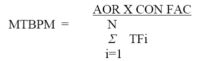
mean_time_between_preventive_maintenance
The mean of the distribution of intervals, measured in hours, rounds, etc., between preventive maintenance actions. This is
one of the four categories of maintenance events contributing to the Mean Time Between Maintenance Actions (MTBMA) , MTBPM
may be calculated by the following formula:
Figure 5 — Mean Time Between Preventive Maintenance Formula
Where:
i = Preventive maintenance action
TFi = Task frequency of the "i" preventive maintenance action
N = Total number of preventive maintenance actions charged against the LCN/ALC item under analysis
AOR = Annual operating requirement
CON FAC = Conversion factor for the LCN/ALC item under analysis
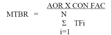
mean_time_between_removals
A measure of the system reliability parameter related to demand for logistics support. The total number of operational units
(e.g., miles, rounds, hours) divided by the total number of items removed from that system during a stated period of time.
This term is defined to exclude removals performed to facilitate other maintenance and removals for product improvement. MTBR
may be calculated by the following formula:
Figure 6 — Mean Time Between Removals Formula
Where:
i = Preventive maintenance action
TFi = Task frequency of the "i" preventive maintenance action
N = Total number of preventive maintenance actions charged
against the LCN/ALC item under analysis
AOR = Annual operating requirement
CON FAC = Conversion factor for the LCN/ALC item under analysis
Note: For a particular task to be applicable, it must meet ALL of the following criteria:
- It must be either a "remove" or a "remove and replace" task.
- It must be categorized as either an "emergency" or an "unscheduled" task.
- The task must be performed by "operator/crew/unit-crew" or "organizational/on equipment/unit-organizational" or by a maintenance
contact team.
- The task cannot be performed to facilitate other maintenance or for product improvement.
mean_time_between_system_aborts
For a system; over a performance measurement/test period, the mean time between system aborts (MTBSA) is the total operating
time of the system divided by the total number of System Abort failures that have occurred during the performance measurement/test
period.
For a population of like systems, during a performance measurement/test period, the total operating time of the population
of like systems divided by the total number of System Abort failures within the population during the performance measurement/test
period. Note: The total operating time of the population is calculated as the summation of the operating time of every like
system in the population over the performance measurement/test period.
- A System Abort is an event that results in the loss or degradation of an essential function(s) that renders the system unable
to enter service or causes immediate removal from service, deadlines the platform, or makes it non-mission capable (a system
abort reduces its utility to the point that it is deemed ineffective/unsafe in its role on the battlefield). System abort
also includes those events that create a personal injury related Category I (catastrophic) or II (critical) hazard as defined
in MIL-STD-882.
- System abort-mobility failures are those failures (operational hardware, and software) that render (deadline) the basic platform/vehicle
mobility subsystem non-mobile/maneuverable, resulting in unsafe operation, or making it non-mission capable.
- A System Abort-Mobility is an event that affects a platform's mobility system(s) and renders the system unable to enter service
or causes immediate removal from service, results in unsafe operation, deadlines the platform, or makes it non-combat capable.
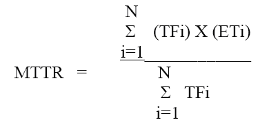
mean_time_to_repair_operational
The total elapsed time (clock hours) for corrective maintenance divided by the total number of corrective maintenance actions
during a given period of time. MTTR may be calculated by the following formula:
Figure 7 — Mean Time to Repair Operational Formula
Where:
i = On equipment corrective maintenance actions
TFi = Task frequency of "i" on equipment maintenance action
N = Total number of on equipment corrective maintenance actions charged against the LCN/ALC item under analysis
ETi = Mean elapsed time of the "i" on equipment corrective maintenance action
MTTR is documented as both technical and operational characteristics. Technical parameters reflect the technical reliability
that the system/equipment must demonstrate. In determining these parameter values, all failures and resultant actions to restore
the item will be considered (e.g., a broken tail light is a technical, but not operational characteristic). Operational parameters
reflect operational reliability and maintainability characteristics that the system must demonstrate. Only operational mission
failures and the resultant tasks are included (e.g., engine failure will result in mission abort that is both an operational
and technical failure).
mean_time_to_repair_technical
See mean_time_to_repair_operational
minimum_equipment_list_indicator
A one-position code that indicates whether the end item can be dispatched on its assigned mission with the item under analysis
inoperative.
mission_phase_code
A one-position code developed by the performing activity that uniquely identifies a Mission Phase/Operational Mode. Codes
are A-Z, 0-9 and *. The asterisk indicates that the information contained for a particular item is applicable to all mission
phases.
mission_phase_operational_mode
A concise statement of the mission phase/operational mode in which the failure occurs. Where subphase, event, or time can
be defined from the system definition and mission profiles, the most definitive timing information should also be described
for the assumed time of failure occurrence.
operating_time
The operating time of the item under analysis per use/mission derived from the system
definition.
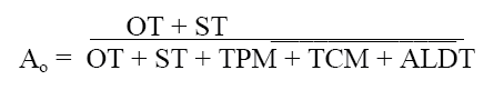
operational_availability
The probability that, when used under stated conditions, a system will operate satisfactorily at any time. This differs from
achieved availability in that Ao includes standby time and administrative and logistic delay time. Ao may be expressed by
the following formula:
Figure 11 — Operational Availability Formula
Where:
OT = Operating time per calendar year
ST = Standby time
TPM = Total preventive maintenance time per calendar year
TCM = Total corrective maintenance time per calendar year
ALDT = Administrative and logistics delay time spent waiting for parts, maintenance personnel, or transportation per calendar
year
percentile
A code that indicates physical and chemical characteristics of an item and identifies weight/fragility and preservative relative
to the packaging of an item. For applicable codes, see MIL-STD-2073-1.
pilot_rework_overhaul_candidate
A code indicating selection status of certain complex assemblies/components considered for pilot rework/overhaul (PR/O) as
part of the preoperational support program.
tems nominated are those that require additional skills, training, support and test equipment, facilities, and technical data
to ensure a rework/overhaul capacity concurrent with government support of the end item. Consideration shall be given to both
intermediate rework and depot level overhaul items.
reliability_availability_and_maintainability_indicator_code
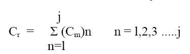
reliability_availability_and_maintainability_item_criticality_number
The sum of the Failure Mode Criticality Numbers related to the failure modes of an item within specific severity classifications
and mission phases. The following formula may be used to calculate Item Cr:
Figure 9 — Reliability Availability and Maintainability Item Criticality Number Formula
Where
Cr = Criticality number for the item
Cm = Failure mode criticality number
n = (l,2,3 .....j)The failure modes in the items that fall under a particular severity classification/mission phase combination
j = Last failure mode in the item under the severity classification/mission phase combination
reliability_availability_and_maintainability_item_function_narrative
A description of the function, specification, and tolerances of the item under analysis, e.g., supply 10 gallons per minute
of hydraulic fluid at 3,000 psi for normal activation of pilot's canopy, hose, main landing gear extension, wheel brakes,
and flap extension.
reliability_availability_and_maintainability_maintenance_concept_narrative
A description of the broad, planned approach to be employed in sustaining the system/equipment at a defined level of readiness,
or in a specified condition in support of the operational requirement. Initially stated by the requiring authority for design
and support planning purposes and is then expanded by performing activity prepared inputs during full-scale development. Provides
the basis for the maintenance plan. Usually includes guidelines pertaining to projected maintenance tasks, levels, and locations:
organic/contractor maintenance work load mix; condition monitoring, fault isolation and testing approach; and, compatibility
with existing support and test equipment, etc. May be influenced or modified as system/equipment development proceeds.
reliability_availability_and_maintainability_maintenance_plan_rationale_narrative
A description of the support data and analysis used in preparation of the maintenance plan. The impact of logistics analyses
including FMECA; RCM; and, level of repair analysis should be documented. In addition, the use of data from like and similar
equipment and lessons learned in formation should also be identified.
reliability_availability_and_maintainability_minimum_equipment_list_narrative
Narrative specifying any limitations on the end item when dispatched on its assigned mission with the item under analysis
inoperative.
reliability_availability_and_maintainability_operational_requirement_indicator
reliability_availability_and_maintainability_qualitative_and_quantitative_maintainability_requirements_narrative
A description of the maintainability design constraints and characteristics that must be considered during the design process,
to include:
- Fail Safe Requirements. A narrative description identifying required fail safe characteristics (i.e., redundancy, back-up
systems, built-in-test and warning equipment, fail safe provisions necessary to protect the equipment from serious damage
after failure, and design features to prevent injury to personnel subsequent to equipment failure).
- Environmental Considerations. A narrative description identifying the applicable environmental conditions within which the
item can operate satisfactorily.This information should include limitations, sensitivity factors, etc., that can affect the
performance and reliability of the item installed in the system/equipment. Limiting factors such as the following should be
considered: shock limits; vibration limits; ambient temperature ranges; operating temperatures in area (compartment) where
item is installed in the system/equipment; humidity factors; altitude factors; magnetic interference; dust and dirt factors;
salts or other corrosive atmosphere; and, light sensitivity. The narrative should include that portion of the system/equipment
environmental impact statement that relates to the effects of the support system on the environment.
- Nuclear Hardened Characteristics. A narrative description identifying the design characteristics that provide minimum nuclear
survivability of the item. No design changes should be made without survivability/vulnerability evaluation to avoid inadvertent
degradation of nuclear hardness.
reliability_availability_and_maintainability_safety_hazard_severity_code
See safety_hazard_severity_code
reliability_centered_maintenance_disposition
The conclusions reached as the outcome of the Reliability Centered Maintenance (RCM) analysis; specifically, the maintenance
requirements that have been determined to be appropriate for the referenced Failure Mode, as the result of the application
of a particular set of RCM logic.
reliability_centered_maintenance_logic_results
This is a 25 block spread format; each logic result will consist of one 1 position block. They are the results of the decision
logic of a reliability centered maintenance (RCM) analysis. Codes will denote a yes or no answer, respectively, to each corresponding
question in the RCM logic tree utilized, or a code as specified by the requiring authority. The specific RCM logic will be
identified by the requiring authority.
|
Code
|
Description
|
|
Y
|
Yes
|
|
N
|
No
|
|
Blank
|
Not Applicable
|
Table — Reliability Centered Maintenance Logic Results
safety_hazard_severity_code
A one-digit code assigned to each identified failure mode for each item analyzed IAW the loss statements below. These codes
are assigned to provide a qualitative measure of the worst potential consequences resulting from design deficiency or item
failure. See MIL-STD-882 for applicable severity classification categories.
security_clearance
A single-position code indicating the type of clearance required to access classified information.
standby_time
The time, in hours per calendar year that a system/equipment is not operating, but is assumed to be operable.
support_concept
A code indicating the status of the in-depth analysis conducted to determine if Contractor Logistics Support (CLS), Interim
Contractor Support (ICS), or Organic Support is the preferred support concept for the item.
system_redesign_accessibility_narrative
A description of whether admission to the various areas of the item under analysis can be achieved with relative ease through
redesign.
system_redesign_connectors_for_ease_of_removal_narrative
A description of the item redesign efforts to include the use of connectors to facilitate removal.
system_redesign_corrosion_and_rust_control_narrative
A description of redesign efforts to ensure adequate corrective or preventive actions have been developed to deter corrosion
or rust damage to the item under analysis.
system_redesign_fault_location_narrative
A description of redesign efforts to facilitate the location of the causes of failures or malfunctions of the item under analysis.
system_redesign_for_self_protection_narrative
A description of redesign efforts to restrict the progress of deterioration after failure of the item under analysis.
system_redesign_labeling_narrative
A description of redesign efforts to ensure parts associated with maintenance are identified and visible with respect to circuit
symbol or part identification.
system_redesign_maintenance_ease_narrative
A description of whether required maintenance can be performed without physical difficulty through redesign.
system_redesign_packaging_and_transportation_narrative
A description of the redesign efforts that have been made to ensure the packaging material and transportation mediums adequately
protect the item under analysis during transport.
system_redesign_safety_narrative
A description of redesign provisions to ensure the conservation of human life and effectiveness, and the prevention of damage
to items, consistent with mission requirements.
system_redesign_skills_narrative
A description of redesign efforts to ensure existing skills are available and sufficient to perform required maintenance on
the item under analysis.
system_redesign_standardization_narrative
A description of whether the redesign of the item under analysis meets the DOD policy to adapt, when possible, to:
- common or compatible operational, administrative and logistic procedures
- common or compatible technical procedures and criteria
- common, compatible, or interchangeable supplies, components, weapons, or equipment
- common or compatible tactical doctrine with corresponding organizational compatibility
system_redesign_test_points_narrative
A description of redesign efforts to include test points on the item under analysis.
system_redesign_training_narrative
A description of redesign efforts to ensure training programs have been planned for the performance of operator/maintainer
tasks on the item under analysis.
task_code
A data chain of six separate data subfields that uniquely identify each operator/maintenance task associated with particular
items under analysis. The first five subfields provide information relative to the performance of the task itself. The sixth
subfield is a task sequence code provided to differentiate tasks with identical entries in the first five subfields.
task_requirement_alternate_logistics_support_analysis_control_number_code
See failure_mode_task_alternate_logistics_support_analysis_control_number_code
task_requirement_logistics_support_analysis_control_number
See failure_mode_task_logistics_support_analysis_control_number
task_requirement_logistics_support_analysis_control_number_type
See failure_mode_task_logistics_support_analysis_control_number_type
task_type
A code that categorizes a maintenance task as corrective, a preventive based on calendar time, or a preventive based on a
rate of use.
|
Code
|
Description
|
|
C
|
Corrective
|
|
P
|
Preventive (calendar)
|
|
U
|
Preventive (usage)
|
Table — Task Type
wearout_life
The operational interval of flight hours, calendar time, or other appropriate independent variable, from initial installation
until an item can no longer perform its intended mission, due to the depletion of some physical property or material. For
a family of items, wearout occurs when the conditional probability of failure (hazard rate) increases with increases of the
independent variable.
Additional terms used in the Help/Information pages.
NOTE These terms are not part of the released specification.