Template:— representing_cad_model (rep_cad_mod)
Capability:representing_properties_numerically |
Date: 2011/10/21 15:52:37
Revision: 1.6
|
![[warning:]](../../../../images/dex/warning.gif) Error T1: There is no template_proxy in the capability representing_properties_numerically for the template representing_cad_model
Error T1: There is no template_proxy in the capability representing_properties_numerically for the template representing_cad_model
This section specifies the template representing_cad_model.
NOTE
The template has been defined in the context of the capability
representing_properties_numerically
which provides an overall description of the
relevant parts of the ISO 10303-239 information model and a description
of related templates.
NOTE
An explanation of a template and the associated instantiation path is
provided in the
Template overview
section.
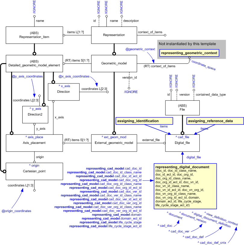
This template describes how to represent a Computer Aided Design model
The EXPRESS-G diagram in
Figure
1
shows the templates and EXPRESS entities that are required
to represent the template
"representing_cad_model".
The text highlighted in blue shows the template parameters.
Figure 1 — An EXPRESS-G representation of the Information model for representing_cad_model
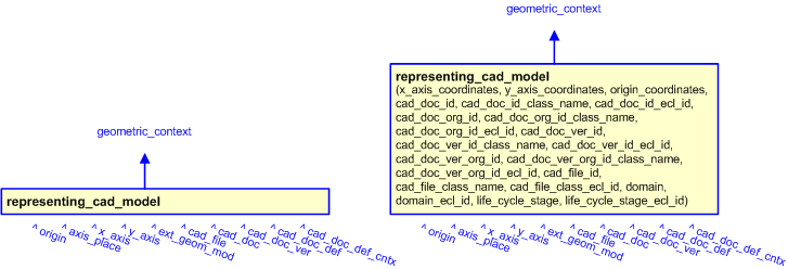
The graphic for the template to be used in other EXPRESS-G diagrams
is shown in Figure
2
below.
Figure 2 — The graphical representation of the representing_cad_model template
The following input parameters are defined for this template:
The coordinate system that provides the context for the CAD model.
The list of 2 or 3 coodinates that provides the direction of the X axis for the CAD model.
The list of 2 or 3 coodinates that provides the direction of the Y axis for the CAD model.
The list of 3 coodinates that provides the origin for the CAD model.
The identifier of the CAD document
The following classes and their sub-classes can be used:
The location of the
External_class_library
that stores the classifications used to classify the CAD document, document_version and document_definition.
The name or identifier of the organization responsible for the CAD document.
The name of the class used to classify the identification (
Identification_assignment)
of the organization responsible for the CAD document.
The following classes and their sub-classes can be used:
The identifier of the
External_class_library storing the
definition of the class used to classify the organization identifier.
The identifier of the CAD document version
The following classes and their sub-classes can be used:
The location of the
External_class_library
that stores the classifications used to classify the CAD document, document_version and document_definition.
The name or identifier of the organization responsible for the CAD document version.
The name of the class used to classify the identification (
Identification_assignment)
of the organization responsible for the CAD document version.
The following classes and their sub-classes can be used:
The identifier of the
External_class_library storing the
definition of the class used to classify the organization identifier.
The identifier of the CAD file managed by the CAD Document
The file type of the CAD document, either a Standards filetype such as AP203 or a CAD system specific type.
The following classes and their sub-classes can be used:
classifications: [AP203-file]Error RDL1: The class AP203-file does not exist in RDL at urn urn:plcs:rdl:std. Check the dexlib/data/refdata/rdl_index.xml
The identifier of the
External_class_library storing the
definition of the class used to classify the Digital_file.
domain (Default=Product_life_cycle_support,Type='CLASS', Optional)
The id of the
External_class_library
used to describe the type of application domain of the view_definition_context instance.
The following classes and their sub-classes can be used:
The identifier of the
External_class_library storing the
definition of the class used to classify the organization identifier.
The id of the
External_class_library
used to describe the type of life cycle stage of the view_definition_context instance.
The following classes and their sub-classes can be used:
The identifier of the
External_class_library storing the
definition of the class used to classify the organization identifier.
The following reference parameters are defined for this template:
Allow the
Cartesian_point
entity instantiated in this path to be referenced when this template is used.
%^target = $representing_cad_model.origin%
Allow the
Axis_placement
entity instantiated in this path to be referenced when this template is used.
Note: The
Axis_placement
entity can be referenced in a template path by:
%^target = $representing_cad_model.axis_place%
Allow the
Direction
entity instantiated in this path to be referenced when this template is used.
Note: The
Direction
entity can be referenced in a template path by:
%^target = $representing_cad_model.x_axis%
where
target
is the parameter to which the
Direction
is bound.
Allow the
Direction
entity instantiated in this path to be referenced when this template is used.
Note: The
Direction
entity can be referenced in a template path by:
%^target = $representing_cad_model.y_axis%
where
target
is the parameter to which the
Direction
is bound.
%^target = $representing_cad_model.ext_geom_mod%
Allow the
Digital_file
entity instantiated in this path to be referenced when this template is used.
Note: The
Digital_file
entity can be referenced in a template path by:
%^target = $representing_cad_model.cad_file%
where
target
is the parameter to which the
Digital_file
is bound.
Allow the
Document
entity instantiated in this path to be referenced when this template is used.
Note: The
Document
entity can be referenced in a template path by:
%^target = $representing_cad_model.cad_doc%
where
target
is the parameter to which the
Document
is bound.
Allow the
Document_version
entity instantiated in this path to be referenced when this template is used.
%^target = $representing_cad_model.cad_doc_ver%
%^target = $representing_cad_model.cad_doc_def%
%^target = $representing_cad_model.cad_doc_def_cntx%
The instantiation path shown below specifies the entities that are to be
instantiated by the template.
A description of templates and the syntax for the instantiation path is
provided in the
Templates Help/Information section.
-- Instantiate Digital_file Digital_file-- Set the unused Digital_file attributes to be ignored Digital_file.id = '/IGNORE'
Digital_file.version = '/IGNORE'
Digital_file.contained_data_type = '/IGNORE'
-- Bind the Digital_file to the parameter ^cad_file %^cad_file =
Digital_file%
-- Identify the Digital_file /
assigning_identification(
items=^cad_file,
id=@cad_file_id,
id_class_name='File_identification_code',
id_ecl_id='urn:plcs:rdl:std',
org_id=@cad_doc_org_id,
org_id_class_name=@cad_doc_org_id_class_name,
org_id_ecl_id=@cad_doc_org_id_ecl_id)/
-- Classify the Digital_file /
assigning_reference_data(
items=^cad_file,
class_name=@cad_file_class_name,
ecl_id=@cad_file_class_ecl_id)/
-- Assign representing_digital_document to Digital_file /
representing_digital_document(
doc_id=@cad_doc_id,
doc_id=@cad_doc_id,
doc_id_class_name=@cad_doc_id_class_name,
doc_id_ecl_id=@cad_doc_id_ecl_id,
doc_org_id=@cad_doc_org_id,
doc_org_id_class_name=@cad_doc_org_id_class_name,
doc_org_id_ecl_id=@cad_doc_org_id_ecl_id,
doc_vn_id=@cad_doc_ver_id,
doc_vn_id_class_name=@cad_doc_ver_id_class_name,
doc_vn_id_ecl_id=@cad_doc_ver_id_ecl_id,
doc_vn_org_id=@cad_doc_ver_org_id,
doc_vn_org_id_class_name=@cad_doc_ver_org_id_class_name,
doc_vn_org_id_ecl_id=@cad_doc_ver_org_id_ecl_id,
domain=@domain,
domain_ecl_id=@domain_ecl_id,
life_cycle_stage=@life_cycle_stage,
life_cycle_stage_ecl_id=@life_cycle_stage_ecl_id,
digital_file=Digital_file)/
-- Instantiate Cartesian_point Cartesian_point-- Bind the Cartesian_point to the parameter ^origin %^origin =
Cartesian_point%
-- Set the unused Cartesian_point attribute to be ignored Cartesian_point.name = '/IGNORE'
-- Set the used Cartesian_point attribute to the corresponding input parameter Cartesian_point.coordinates =
@origin_coordinates-- Instantiate Direction of X axis Direction-- Bind the Direction to the parameter ^x_axis %^x_axis =
Direction%
-- Set the unused Direction attribute to be ignored Direction.name = '/IGNORE'
-- Set the used Direction attribute to the corresponding input parameter Direction.coordinates =
@x_axis_coordinates-- Instantiate Direction of Y axis Direction-- Bind the Direction to the parameter ^y_axis %^y_axis =
Direction%
-- Set the unused Direction attribute to be ignored Direction.name = '/IGNORE'
-- Set the used Direction attribute to the corresponding input parameter Direction.coordinates =
@y_axis_coordinates-- Instantiate Axis_placement Axis_placement-- Bind the Axis_placement to the parameter ^axis_place %^axis_place =
Axis_placement%
-- Set the unused Axis_placement attribute to be ignored Axis_placement.name = '/IGNORE'
-- Instantiate the used Axis_placement relationships within the template Axis_placement.origin ->
^origin
Axis_placement.x_axis ->
^x_axis
Axis_placement.y_axis ->
^y_axis
-- Instantiate External_geometric_model External_geometric_model-- Set the unused External_geometric_model attributes to be ignored External_geometric_model.id = '/IGNORE'
External_geometric_model.name = '/IGNORE'
External_geometric_model.description = '/IGNORE'
External_geometric_model.version_id = '/IGNORE'
-- leave the Model_extent unset -- Set the used External_geometric_model relationship to the corresponding input parameters External_geometric_model.context_of_items ->
@geometric_context-- Instantiate the used External_geometric_model relationships within the template External_geometric_model.items ->
^axis_place
External_geometric_model.external_file ->
^cad_file
The following entities are instantiated with attributes as specified:
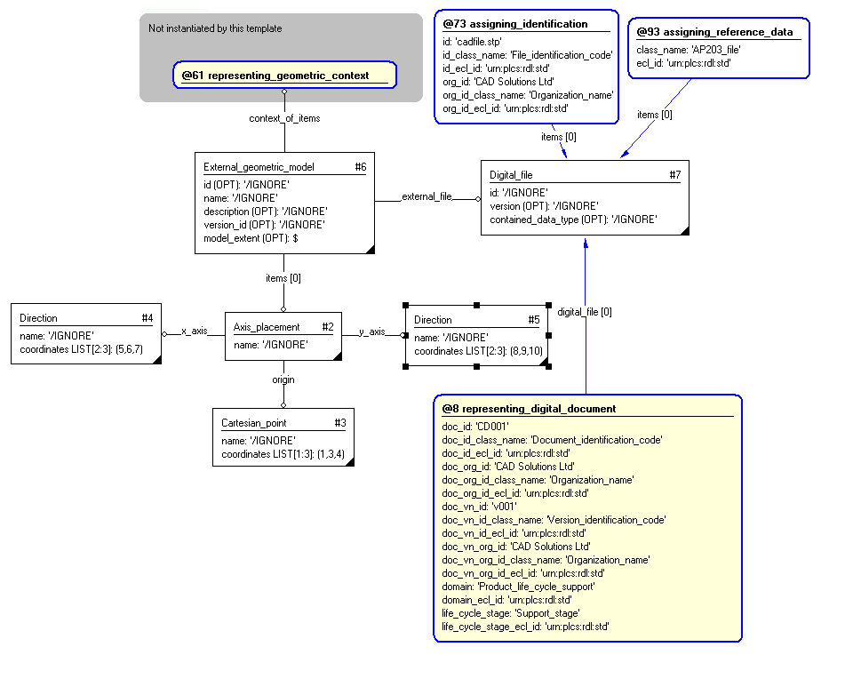
The instance diagram in Figure
3
shows an example of the EXPRESS entities and templates that are instantiated by the template:
/representing_cad_model(geometric_context='', x_axis_coordinates='5, 6, 7', y_axis_coordinates='8, 9, 10', origin_coordinates='1, 2, 3', cad_doc_id='CD001', cad_doc_id_class_name='Document_identification_code', cad_doc_id_ecl_id='urn:plcs:rdl:std', cad_doc_org_id='CAD Solutions Ltd', cad_doc_org_id_class_name='Organization_name', cad_doc_org_id_ecl_id='urn:plcs:rdl:std', cad_doc_ver_id='v001', cad_doc_ver_id_class_name='Version_identification_code', cad_doc_ver_id_ecl_id='urn:plcs:rdl:std', cad_doc_ver_org_id='CAD Solutions Ltd', cad_doc_ver_org_id_class_name='Organization_name', cad_doc_ver_org_id_ecl_id='urn:plcs:rdl:std', cad_file_id='cadfile.stp', cad_file_class_name='AP203_file', cad_file_class_ecl_id='urn:plcs:rdl:std', domain='Product_life_cycle_support', domain_ecl_id='urn:plcs:rdl:std', life_cycle_stage='Support_stage', life_cycle_stage_ecl_id='urn:plcs:rdl:std')/
(an illustration of the consolidated representing_cad_model template is shown in
Figure
4 below.)
Figure 3 — Entities instantiated by representing_cad_model template
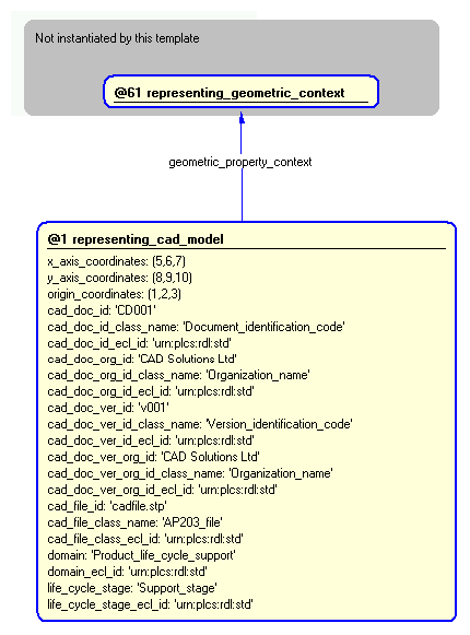
The instance diagram in
Figure
4
shows the graphic symbol for the template that is to be
used in other instance diagrams. The example template is:
/representing_cad_model(geometric_context='', x_axis_coordinates='5, 6, 7', y_axis_coordinates='8, 9, 10', origin_coordinates='1, 2, 3', cad_doc_id='CD001', cad_doc_id_class_name='Document_identification_code', cad_doc_id_ecl_id='urn:plcs:rdl:std', cad_doc_org_id='CAD Solutions Ltd', cad_doc_org_id_class_name='Organization_name', cad_doc_org_id_ecl_id='urn:plcs:rdl:std', cad_doc_ver_id='v001', cad_doc_ver_id_class_name='Version_identification_code', cad_doc_ver_id_ecl_id='urn:plcs:rdl:std', cad_doc_ver_org_id='CAD Solutions Ltd', cad_doc_ver_org_id_class_name='Organization_name', cad_doc_ver_org_id_ecl_id='urn:plcs:rdl:std', cad_file_id='cadfile.stp', cad_file_class_name='AP203_file', cad_file_class_ecl_id='urn:plcs:rdl:std', domain='Product_life_cycle_support', domain_ecl_id='urn:plcs:rdl:std', life_cycle_stage='Support_stage', life_cycle_stage_ecl_id='urn:plcs:rdl:std')/
Figure 4 — Instantiation of representing_cad_model template
Characterizations
No common characterizations of the template
representing_cad_model
have been identified. However, the ISO 10303-239 EXPRESS model
may enable other assignments to the entities instantiated by the template.