| Capability (C079):— representing_properties_numerically |
Date: 2012/05/21 19:35:57
Revision: 1.47
|
This section provides a business level overview of this capability.
In STEP, a property may have one or more representations. The numeric representation of a property provides its value (or
value range) and
the unit of measure for the value (or values). There may be more than one
representation for a given property, which allows multiple ways to describe
the same property:
EXAMPLE
a mass property may be expressed as 1 kg or as
2.2 lbs
NOTE
The representation of ranges of numerical values is
described in C084: representing_property_value_ranges.
In AP239, there are three types of property assignment
C076: assigning_product_properties
,
C077: assigning_process_properties
,
C078: assigning_resource_properties
, but all can be represented using this capability.
A property is a qualitative or quantitative characteristic that something may possess. ISO10303 uses
properties in many ways:
EXAMPLE
Properties assigned to parts (weight, dimensions, material, etc.)
EXAMPLE
Properties assigned to activities (e.g. duration)
etc.
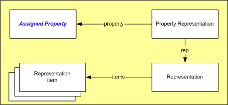
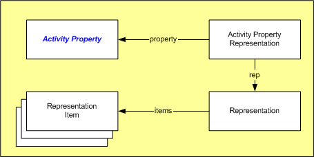
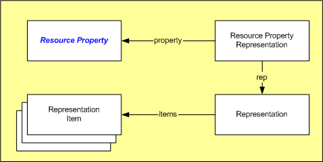
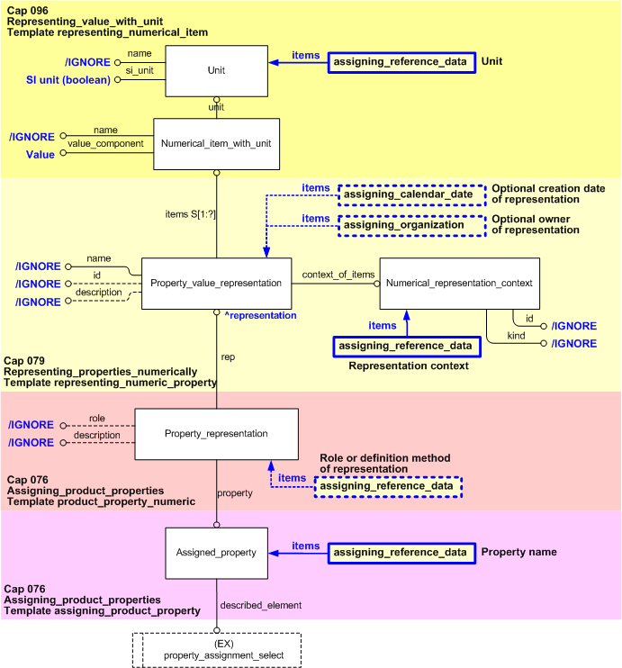
Properties are represented in different ways, depending on the type of the property:
Figure 1 — Representing a Product Property
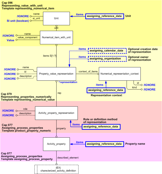
Figure 2 — Representing a Process Property
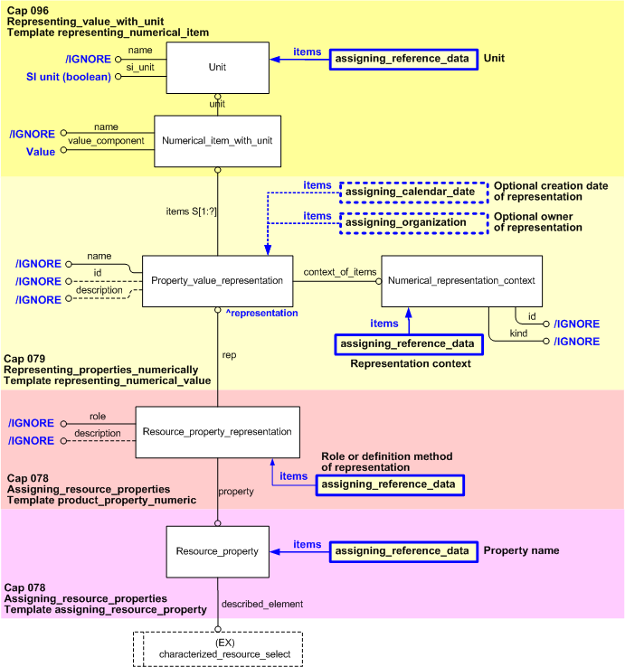
Figure 3 — Representing a Resource Property
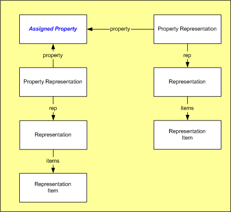
There may be multiple representations of the same property:
Figure 4 — Multiple Representations of a Property
A representation may be made up of several representation items
EXAMPLE
a mass property may be represented as 1kg and also represented as 2.2 lbs
The STEP (ISO10303) standard uses the concept of representation context. All values in the same context are deemed to be related.
This idea originates from geometrical
representations, so that common coordinates systems could be identified. For numeric properties, the representation context
can be used to group properties of a similar type - e.g.
mass properties, time properties, etc. However, the extensive use of classification and reference data in PLCS has rendered
the use of representation context less important.
This section provides an overview of the information model that supports
this capability.
The EXPRESS_G model and Capabilities used for representing numerical product properties is shown in
Figure 5, Figure 6 and Figure 7 below:
Figure 5 — Entities Used for Numerical Product Property Representation
The EXPRESS_G model and Capabilities used for representing numerical process properties is shown in
Figure 6 below:
Figure 6 — Entities Used for Numerical Process Property Representation
The EXPRESS_G model and Capabilities used for representing numerical resource properties is shown in
Figure 7 below:
Figure 7 — Entities Used for Numerical Resource Property Representation
The following templates are used in the diagrams in Figure 5, Figure 6,
and Figure 7 above:
To represent a numerical property value, the following entities are required:
-
Numerical_item_with_unit
- This entity is used to describe the value of a property, with a reference to the unit of measure
(described in C096: representing_value_with_unit).
-
Unit
- This entity is used to describe a unit of measure (described in C096: representing_value_with_unit).
AP239 mandates that reference data should be used to
classify instances of this entity.
-
Property_value_representation
- This entity is a subtype of
Representation
that is used to collect together the values
(Numerical_item_with_unit)
of the property (not the same as having multiple representations of a property, e.g. a numerical value and
a textual value).
In almost every case, there will only be one value for a property. This entity is described in this capability.
-
Numerical_representation_context
- This entity describes the context for the representation (described in this capability).
AP239 mandates that reference data should be used to
classify instances of this entity. Only one instance should be created for each context.
The context is used to group particular kinds of representation, in order to enable comparison of representation
values
- e.g. mass measurement, accounting procedures, etc.
The Property_value_representation
is linked to the item it whose property it represents using one of the following entities:
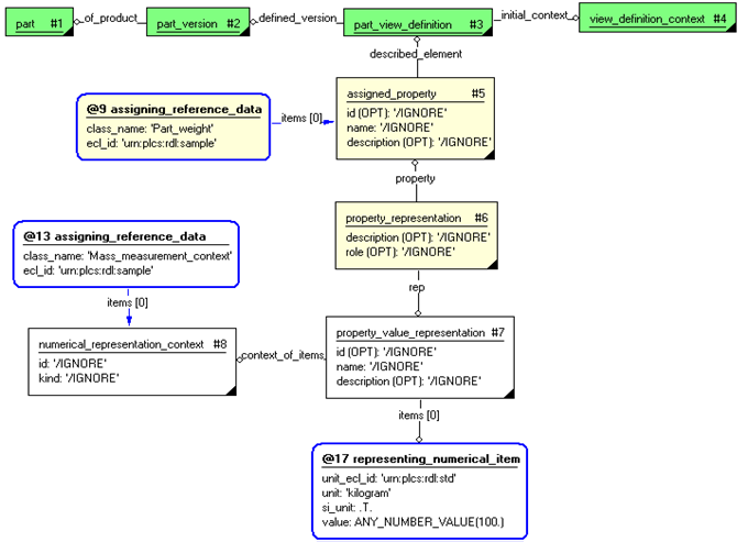
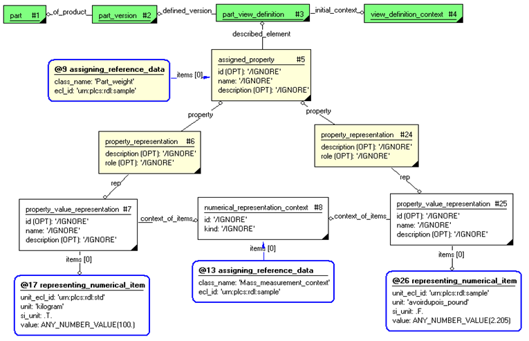
Figure 8 shows an example instantiation of a numeric property which represents the mass of a part.
Figure 8 — Instances Used for Numeric Property Representation
A given property may have multiple representations, e.g. a numerical value representation and a textual representation.
This capability is used for one single numerical property representation (value) but it may be used several times.
Figure 9 shows an example instantiation of a numeric property which is represented in two different ways
(pounds and kilograms).
Figure 9 — Instances Used for Multiple Numeric Property Representation
The use of external reference data for Units
is described in Capability C096: representing_value_with_unit.
Date and Time Assignment
Recording the date and time at which a property was given a value (i.e. represented) is optional, but highly recommended.
This allows a history of property values to be recorded - i.e. the same property may have several
representations with different dates and times assigned to them.
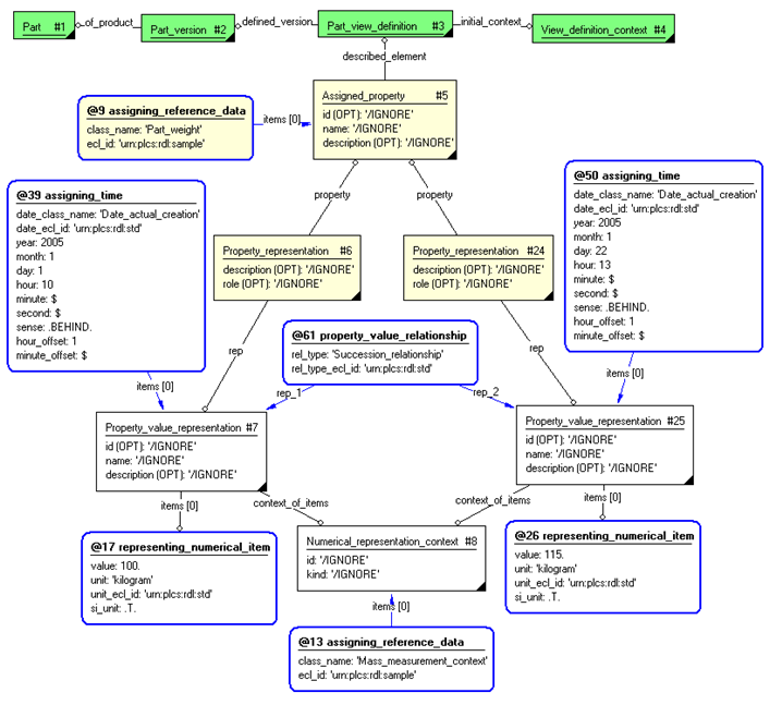
Figure 10 — A property changing over time
In Figure 10, a part's mass is changed from 100kg to 115kg. Note that template
property_value_relationship
containing a classified
Representation_relationship
entity instance is used to relate the two representations, and that each representation has date and
time assigned (see C036: assigning_date_time).
Person and Organization Assignment
It is optional but highly recommended to record the person (and their organization) who assigned the property
value.
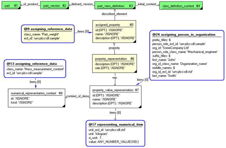
Figure 11 — Assigning Person and Organization to a Property Representation
In Figure 11, the instances establish that the property value was set by a person in an organization.
The following sections define a set of templates for the capability,
where a template is a specification of a set of entities that need to
be instantiated to represent a given set of information.
This section specifies the template representing_numeric_property.
NOTE
An explanation of a template and the associated instantiation path is
provided in the
Template overview
section.
This template describes how to represent a single numerical value with unit for any property.
It provides a context for the value, and the representation may be further characterized
by assigning time and organization.
EXAMPLE
The number of hours taken to perform some action.
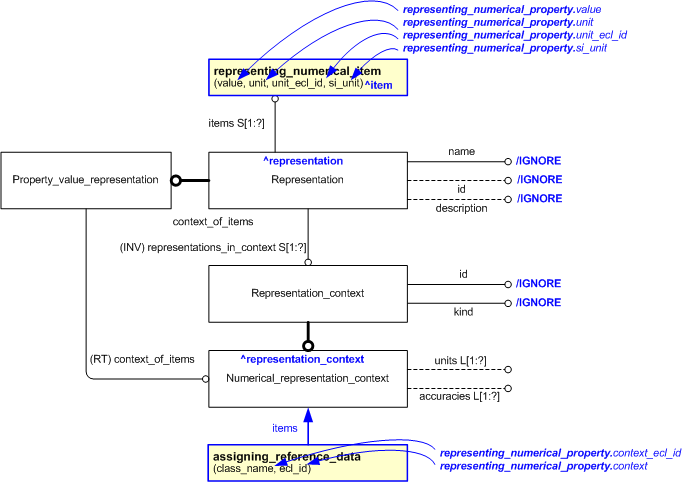
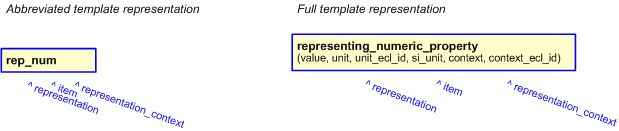
The EXPRESS-G diagram in
Figure
1
shows the templates and EXPRESS entities that are required
to represent the template
"representing_numeric_property".
The text highlighted in blue shows the template parameters.
Figure 1 — An EXPRESS-G representation of the Information model for representing_numeric_property
The graphic for the template to be used in other EXPRESS-G diagrams
is shown in Figure
2
below.
Figure 2 —
The graphical representation of representing_numeric_property template
The following input parameters are defined for this template:
The value of the property. The datatype is always 'any_number_value'
and should not be registered together with the value, i.e. enter the
value as a number, without datatype.
The class name of the unit in which the value is expressed.
The following classes and their sub-classes can be used:
The identifier of the
External_class_library
storing the definition of the class referenced by the parameter @unit.
si_unit (Default=false,Type='BOOLEAN')
Value should be set to true if the unit is a SI base unit defined by ISO, i.e.
kilogram (kg) for Mass,
second (s) for Time,
metre (m) for Displacement,
ampere (A) for Electrical current,
kelvin (K) for Temperature,
mole (mol) for Amount of substance, and
candela (cd) for Luminous intensity. If this is not the case it should be set to false.
Note that the representation of true and false depends on exchange format. In Part 11 (a STEP file) true is
represented by the string ".T.", and false by ".F.", while in Part 28 (XML) they are represented by text
strings "true"
and "false".
The following classes and their sub-classes can be used:
The identifier of the
External_class_library
storing the definition of the class referenced by the parameter @context.
The following reference parameters are defined for this template:
%^target = $representing_numeric_property.representation%
%^target = $representing_numeric_property.item%
%^target = $representing_numeric_property.representation_context%
The following parameter combinations specify a uniqueness constraint:
Unique constraint: Unique Numerical_representation_context
The instantiation path shown below specifies the entities that are to be
instantiated by the template.
The following entities are instantiated with attributes as specified:
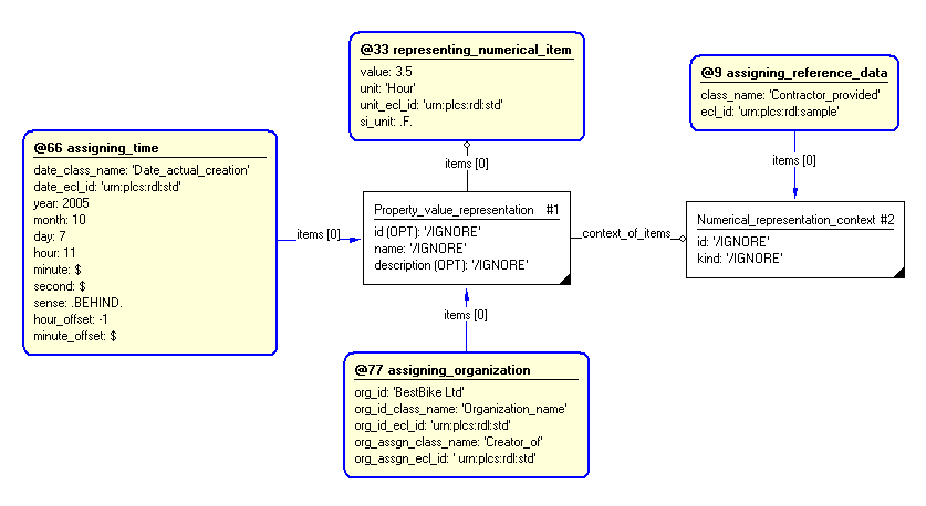
The instance diagram in Figure
3
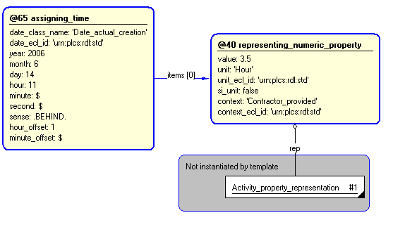
shows an example of the EXPRESS entities and templates that are instantiated by the template:
/representing_numeric_property(value='any_number_value(3.5)', si_unit='false', unit_class_name='Hour', unit_ecl_id='urn:plcs:rdl:std', rep_class_name='Contractor_provided', rep_ecl_id='urn:plcs:rdl:sample')/
(an illustration of the consolidated representing_numeric_property template is shown in
Figure
4 below.)
Note that the templates
assigning_time and
assigning_organization
are used in the diagram.
Namely:
@66 /assigning_time(date_class_name='Date_actual_creation', date_ecl_id='urn:plcs:rdl:std', year='2005', month='10', day='7', hour='11', sense='behind', hour_offset='-1', items='#1')/
and:
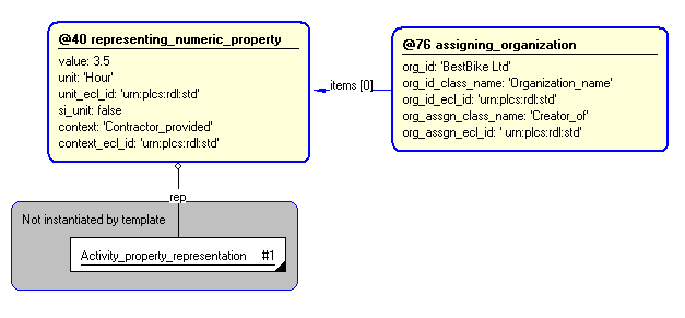
@77 /assigning_organization(org_id='BestBike Ltd', org_id_class_name='Organization_name', org_id_ecl_id='urn:plcs:rdl:std', org_assgn_class_name='Creator_of', org_assgn_ecl_id='urn:plcs:rdl:std', items='#1')/
Figure 3 — Entities instantiated by representing_numeric_property template
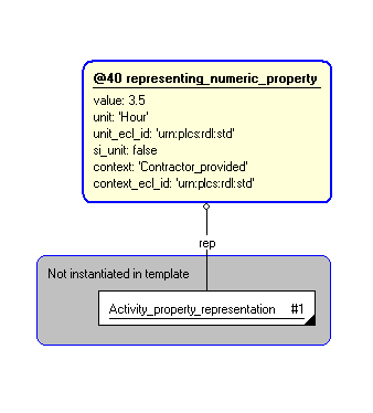
The instance diagram in
Figure
4
shows the graphic symbol for the template that is to be
used in other instance diagrams. The example template is:
/representing_numeric_property(value='any_number_value(3.5)', si_unit='false', unit_class_name='Hour', unit_ecl_id='urn:plcs:rdl:std', rep_class_name='Contractor_provided', rep_ecl_id='urn:plcs:rdl:sample')/
Figure 4 — Instantiation of representing_numeric_property template
The following section details how the
representing_numeric_property
template can be optionally characterized by assigning
other constructs to it. These are characterizations commonly
applied to the template. The ISO 10303-239 EXPRESS model may enable
other assignments to the entities instantiated by the template.
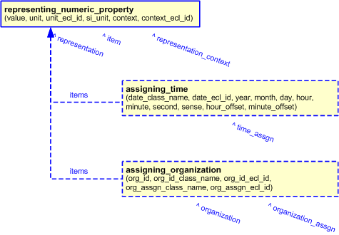
The EXPRESS-G diagram in Figure
5
shows the possible characterizations of the template
"representing_numeric_property".
Figure 5 — Characterizations for representing_numeric_property template
The following characterizations may apply:
Characterization Assigning date and time
NOTE this characterization is optional.
Characterization Assigning organization
NOTE this characterization is optional.
This section specifies the template representing_geometric_context.
NOTE
An explanation of a template and the associated instantiation path is
provided in the
Template overview
section.
This template describes how to represent a geometric context.
The EXPRESS-G diagram in
Figure
1
shows the templates and EXPRESS entities that are required
to represent the template
"representing_geometric_context".
The text highlighted in blue shows the template parameters.
Figure 1 — An EXPRESS-G representation of the Information model for representing_geometric_context
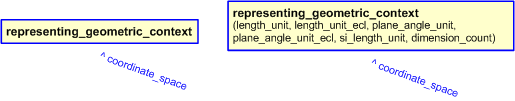
The graphic for the template to be used in other EXPRESS-G diagrams
is shown in Figure
2
below.
Figure 2 — The graphical representation of the representing_geometric_context template
The following input parameters are defined for this template:
The following classes and their sub-classes can be used:
The identifier of the
External_class_library
that holds the definition of the class referenced by the parameter @length_unit.
The following classes and their sub-classes can be used:
The identifier of the
External_class_library
that holds the definition of the class referenced by the parameter @plane_angle_unit.
Value should be set to true if the unit is a SI base unit defined by ISO, i.e.
kilogram (kg) for Mass,
second (s) for Time,
metre (m) for Displacement,
ampere (A) for Electrical current,
kelvin (K) for Temperature,
mole (mol) for Amount of substance, and
candela (cd) for Luminous intensity. If this is not the case it should be set to false.
Note that the representation of true and false depends on exchange format. In Part 11 (a STEP file) true is
represented by the string ".T.", and false by ".F.", while in Part 28 (XML) they are represented by text strings
"true"
and "false".
The number of dimensions (2 or 3) of the geometric context.
The following reference parameters are defined for this template:
%^target = $representing_geometric_context.coordinate_space%
The instantiation path shown below specifies the entities that are to be
instantiated by the template.
The following entities are instantiated with attributes as specified:
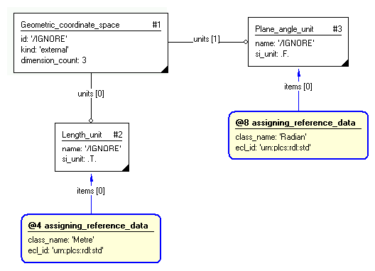
The instance diagram in Figure
3
shows an example of the EXPRESS entities and templates that are instantiated by the template:
/representing_geometric_context(length_unit='Metre', length_unit_ecl='urn:plcs:rdl:std', plane_angle_unit='Radian', plane_angle_unit_ecl='urn:plcs:rdl:std', si_length_unit='true', dimension_count='3')/
(an illustration of the consolidated representing_geometric_context template is shown in
Figure
4 below.)
Figure 3 — Entities instantiated by representing_geometric_context template
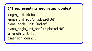
The instance diagram in
Figure
4
shows the graphic symbol for the template that is to be
used in other instance diagrams. The example template is:
/representing_geometric_context(length_unit='Metre', length_unit_ecl='urn:plcs:rdl:std', plane_angle_unit='Radian', plane_angle_unit_ecl='urn:plcs:rdl:std', si_length_unit='true', dimension_count='3')/
Figure 4 — Instantiation of representing_geometric_context template
No common characterizations of the template
representing_geometric_context
have been identified. However, the ISO 10303-239 EXPRESS model
may enable other assignments to the entities instantiated by the template.
This section specifies the template representing_geometric_property.
NOTE
An explanation of a template and the associated instantiation path is
provided in the
Template overview
section.
This template describes how to a represent property in terms of a Cartesian point.
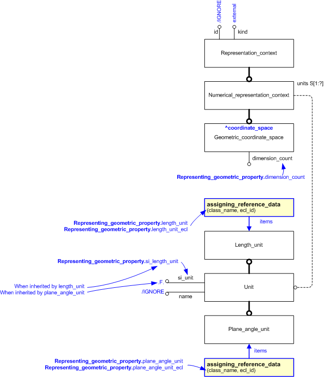
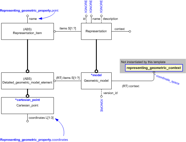
The EXPRESS-G diagram in
Figure
1
shows the templates and EXPRESS entities that are required
to represent the template
"representing_geometric_property".
The text highlighted in blue shows the template parameters.
Figure 1 — An EXPRESS-G representation of the Information model for representing_geometric_property
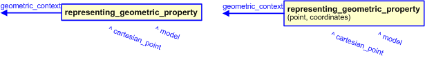
The graphic for the template to be used in other EXPRESS-G diagrams
is shown in Figure
2
below.
Figure 2 — The graphical representation of the representing_geometric_property template
The following input parameters are defined for this template:
The coordinate space that provides the context for the CAD model.
The name of the cartesian point.
A list of the three (X, Y, and Z) coordiantes of the cartesian point.
The following reference parameters are defined for this template:
Allow the
Cartesian_point
entity instantiated in this path to be referenced when this template is used.
%^target = $representing_geometric_property.cartesian_point%
Allow the
Geometric_model
entity instantiated in this path to be referenced when this template is used.
%^target = $representing_geometric_property.model%
The instantiation path shown below specifies the entities that are to be
instantiated by the template.
The following entities are instantiated with attributes as specified:
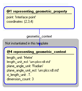
The instance diagram in Figure
3
shows an example of the EXPRESS entities and templates that are instantiated by the template:
/representing_geometric_property(geometric_context='', point='Interface point', coordinates='2, 3, 4')/
(an illustration of the consolidated representing_geometric_property template is shown in
Figure
4 below.)
Figure 3 — Entities instantiated by representing_geometric_property template
The instance diagram in
Figure
4
shows the graphic symbol for the template that is to be
used in other instance diagrams. The example template is:
/representing_geometric_property(geometric_context='', point='Interface point', coordinates='2, 3, 4')/
Figure 4 — Instantiation of representing_geometric_property template
No common characterizations of the template
representing_geometric_property
have been identified. However, the ISO 10303-239 EXPRESS model
may enable other assignments to the entities instantiated by the template.
This section specifies the template representing_cad_model.
NOTE
An explanation of a template and the associated instantiation path is
provided in the
Template overview
section.
This template describes how to represent a Computer Aided Design model
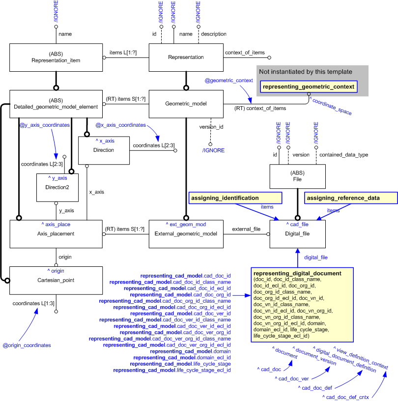
The EXPRESS-G diagram in
Figure
1
shows the templates and EXPRESS entities that are required
to represent the template
"representing_cad_model".
The text highlighted in blue shows the template parameters.
Figure 1 — An EXPRESS-G representation of the Information model for representing_cad_model
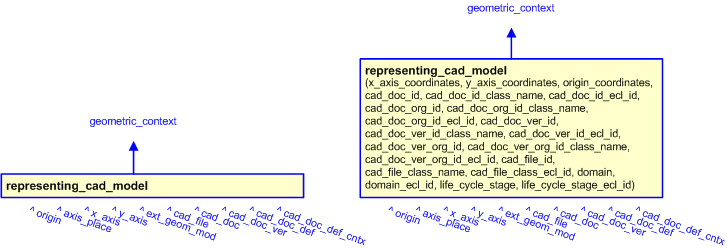
The graphic for the template to be used in other EXPRESS-G diagrams
is shown in Figure
2
below.
Figure 2 — The graphical representation of the representing_cad_model template
The following input parameters are defined for this template:
The coordinate system that provides the context for the CAD model.
The list of 2 or 3 coodinates that provides the direction of the X axis for the CAD model.
The list of 2 or 3 coodinates that provides the direction of the Y axis for the CAD model.
The list of 3 coodinates that provides the origin for the CAD model.
The identifier of the CAD document
The following classes and their sub-classes can be used:
The location of the
External_class_library
that stores the classifications used to classify the CAD document, document_version and document_definition.
The name or identifier of the organization responsible for the CAD document.
The name of the class used to classify the identification (
Identification_assignment)
of the organization responsible for the CAD document.
The following classes and their sub-classes can be used:
The identifier of the
External_class_library storing the
definition of the class used to classify the organization identifier.
The identifier of the CAD document version
The following classes and their sub-classes can be used:
The location of the
External_class_library
that stores the classifications used to classify the CAD document, document_version and document_definition.
The name or identifier of the organization responsible for the CAD document version.
The name of the class used to classify the identification (
Identification_assignment)
of the organization responsible for the CAD document version.
The following classes and their sub-classes can be used:
The identifier of the
External_class_library storing the
definition of the class used to classify the organization identifier.
The identifier of the CAD file managed by the CAD Document
The file type of the CAD document, either a Standards filetype such as AP203 or a CAD system specific type.
The following classes and their sub-classes can be used:
classifications: [AP203-file]![[warning:]](../../../../images/dex/warning.gif) Error RDL1: The class AP203-file does not exist in RDL at urn urn:plcs:rdl:std. Check the dexlib/data/refdata/rdl_index.xml
Error RDL1: The class AP203-file does not exist in RDL at urn urn:plcs:rdl:std. Check the dexlib/data/refdata/rdl_index.xml
The identifier of the
External_class_library storing the
definition of the class used to classify the Digital_file.
domain (Default=Product_life_cycle_support,Type='CLASS', Optional)
The id of the
External_class_library
used to describe the type of application domain of the view_definition_context instance.
The following classes and their sub-classes can be used:
The identifier of the
External_class_library storing the
definition of the class used to classify the organization identifier.
The id of the
External_class_library
used to describe the type of life cycle stage of the view_definition_context instance.
The following classes and their sub-classes can be used:
The identifier of the
External_class_library storing the
definition of the class used to classify the organization identifier.
The following reference parameters are defined for this template:
Allow the
Cartesian_point
entity instantiated in this path to be referenced when this template is used.
%^target = $representing_cad_model.origin%
Allow the
Axis_placement
entity instantiated in this path to be referenced when this template is used.
Note: The
Axis_placement
entity can be referenced in a template path by:
%^target = $representing_cad_model.axis_place%
Allow the
Direction
entity instantiated in this path to be referenced when this template is used.
Note: The
Direction
entity can be referenced in a template path by:
%^target = $representing_cad_model.x_axis%
where
target
is the parameter to which the
Direction
is bound.
Allow the
Direction
entity instantiated in this path to be referenced when this template is used.
Note: The
Direction
entity can be referenced in a template path by:
%^target = $representing_cad_model.y_axis%
where
target
is the parameter to which the
Direction
is bound.
%^target = $representing_cad_model.ext_geom_mod%
Allow the
Digital_file
entity instantiated in this path to be referenced when this template is used.
Note: The
Digital_file
entity can be referenced in a template path by:
%^target = $representing_cad_model.cad_file%
where
target
is the parameter to which the
Digital_file
is bound.
Allow the
Document
entity instantiated in this path to be referenced when this template is used.
Note: The
Document
entity can be referenced in a template path by:
%^target = $representing_cad_model.cad_doc%
where
target
is the parameter to which the
Document
is bound.
Allow the
Document_version
entity instantiated in this path to be referenced when this template is used.
%^target = $representing_cad_model.cad_doc_ver%
%^target = $representing_cad_model.cad_doc_def%
%^target = $representing_cad_model.cad_doc_def_cntx%
The instantiation path shown below specifies the entities that are to be
instantiated by the template.
-- Instantiate Digital_file Digital_file-- Set the unused Digital_file attributes to be ignored Digital_file.id = '/IGNORE'
Digital_file.version = '/IGNORE'
Digital_file.contained_data_type = '/IGNORE'
-- Bind the Digital_file to the parameter ^cad_file %^cad_file =
Digital_file%
-- Identify the Digital_file /
assigning_identification(
items=^cad_file,
id=@cad_file_id,
id_class_name='File_identification_code',
id_ecl_id='urn:plcs:rdl:std',
org_id=@cad_doc_org_id,
org_id_class_name=@cad_doc_org_id_class_name,
org_id_ecl_id=@cad_doc_org_id_ecl_id)/
-- Classify the Digital_file /
assigning_reference_data(
items=^cad_file,
class_name=@cad_file_class_name,
ecl_id=@cad_file_class_ecl_id)/
-- Assign representing_digital_document to Digital_file /
representing_digital_document(
doc_id=@cad_doc_id,
doc_id=@cad_doc_id,
doc_id_class_name=@cad_doc_id_class_name,
doc_id_ecl_id=@cad_doc_id_ecl_id,
doc_org_id=@cad_doc_org_id,
doc_org_id_class_name=@cad_doc_org_id_class_name,
doc_org_id_ecl_id=@cad_doc_org_id_ecl_id,
doc_vn_id=@cad_doc_ver_id,
doc_vn_id_class_name=@cad_doc_ver_id_class_name,
doc_vn_id_ecl_id=@cad_doc_ver_id_ecl_id,
doc_vn_org_id=@cad_doc_ver_org_id,
doc_vn_org_id_class_name=@cad_doc_ver_org_id_class_name,
doc_vn_org_id_ecl_id=@cad_doc_ver_org_id_ecl_id,
domain=@domain,
domain_ecl_id=@domain_ecl_id,
life_cycle_stage=@life_cycle_stage,
life_cycle_stage_ecl_id=@life_cycle_stage_ecl_id,
digital_file=Digital_file)/
-- Instantiate Cartesian_point Cartesian_point-- Bind the Cartesian_point to the parameter ^origin %^origin =
Cartesian_point%
-- Set the unused Cartesian_point attribute to be ignored Cartesian_point.name = '/IGNORE'
-- Set the used Cartesian_point attribute to the corresponding input parameter Cartesian_point.coordinates =
@origin_coordinates-- Instantiate Direction of X axis Direction-- Bind the Direction to the parameter ^x_axis %^x_axis =
Direction%
-- Set the unused Direction attribute to be ignored Direction.name = '/IGNORE'
-- Set the used Direction attribute to the corresponding input parameter Direction.coordinates =
@x_axis_coordinates-- Instantiate Direction of Y axis Direction-- Bind the Direction to the parameter ^y_axis %^y_axis =
Direction%
-- Set the unused Direction attribute to be ignored Direction.name = '/IGNORE'
-- Set the used Direction attribute to the corresponding input parameter Direction.coordinates =
@y_axis_coordinates-- Instantiate Axis_placement Axis_placement-- Bind the Axis_placement to the parameter ^axis_place %^axis_place =
Axis_placement%
-- Set the unused Axis_placement attribute to be ignored Axis_placement.name = '/IGNORE'
-- Instantiate the used Axis_placement relationships within the template Axis_placement.origin ->
^origin
Axis_placement.x_axis ->
^x_axis
Axis_placement.y_axis ->
^y_axis
-- Instantiate External_geometric_model External_geometric_model-- Set the unused External_geometric_model attributes to be ignored External_geometric_model.id = '/IGNORE'
External_geometric_model.name = '/IGNORE'
External_geometric_model.description = '/IGNORE'
External_geometric_model.version_id = '/IGNORE'
-- leave the Model_extent unset -- Set the used External_geometric_model relationship to the corresponding input parameters External_geometric_model.context_of_items ->
@geometric_context-- Instantiate the used External_geometric_model relationships within the template External_geometric_model.items ->
^axis_place
External_geometric_model.external_file ->
^cad_file
The following entities are instantiated with attributes as specified:
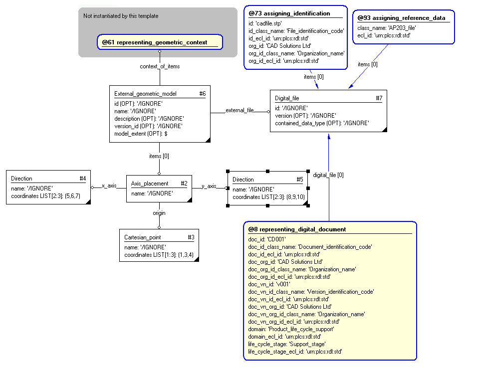
The instance diagram in Figure
3
shows an example of the EXPRESS entities and templates that are instantiated by the template:
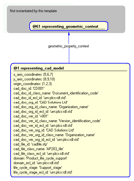
/representing_cad_model(geometric_context='', x_axis_coordinates='5, 6, 7', y_axis_coordinates='8, 9, 10', origin_coordinates='1, 2, 3', cad_doc_id='CD001', cad_doc_id_class_name='Document_identification_code', cad_doc_id_ecl_id='urn:plcs:rdl:std', cad_doc_org_id='CAD Solutions Ltd', cad_doc_org_id_class_name='Organization_name', cad_doc_org_id_ecl_id='urn:plcs:rdl:std', cad_doc_ver_id='v001', cad_doc_ver_id_class_name='Version_identification_code', cad_doc_ver_id_ecl_id='urn:plcs:rdl:std', cad_doc_ver_org_id='CAD Solutions Ltd', cad_doc_ver_org_id_class_name='Organization_name', cad_doc_ver_org_id_ecl_id='urn:plcs:rdl:std', cad_file_id='cadfile.stp', cad_file_class_name='AP203_file', cad_file_class_ecl_id='urn:plcs:rdl:std', domain='Product_life_cycle_support', domain_ecl_id='urn:plcs:rdl:std', life_cycle_stage='Support_stage', life_cycle_stage_ecl_id='urn:plcs:rdl:std')/
(an illustration of the consolidated representing_cad_model template is shown in
Figure
4 below.)
Figure 3 — Entities instantiated by representing_cad_model template
The instance diagram in
Figure
4
shows the graphic symbol for the template that is to be
used in other instance diagrams. The example template is:
/representing_cad_model(geometric_context='', x_axis_coordinates='5, 6, 7', y_axis_coordinates='8, 9, 10', origin_coordinates='1, 2, 3', cad_doc_id='CD001', cad_doc_id_class_name='Document_identification_code', cad_doc_id_ecl_id='urn:plcs:rdl:std', cad_doc_org_id='CAD Solutions Ltd', cad_doc_org_id_class_name='Organization_name', cad_doc_org_id_ecl_id='urn:plcs:rdl:std', cad_doc_ver_id='v001', cad_doc_ver_id_class_name='Version_identification_code', cad_doc_ver_id_ecl_id='urn:plcs:rdl:std', cad_doc_ver_org_id='CAD Solutions Ltd', cad_doc_ver_org_id_class_name='Organization_name', cad_doc_ver_org_id_ecl_id='urn:plcs:rdl:std', cad_file_id='cadfile.stp', cad_file_class_name='AP203_file', cad_file_class_ecl_id='urn:plcs:rdl:std', domain='Product_life_cycle_support', domain_ecl_id='urn:plcs:rdl:std', life_cycle_stage='Support_stage', life_cycle_stage_ecl_id='urn:plcs:rdl:std')/
Figure 4 — Instantiation of representing_cad_model template
No common characterizations of the template
representing_cad_model
have been identified. However, the ISO 10303-239 EXPRESS model
may enable other assignments to the entities instantiated by the template.
This capability
"Representing Numeric Properties" is related to the
following capabilities:
This capability
"Representing Numeric Properties" is dependent on
the following capabilities:
The following classes of reference data are required for this capability:
[Area_unit]
Error RDL1: The class Area_unit does not exist in RDL at URI urn:plcs:rdl:std. Check the dexlib/data/refdata/rdl_index.xml
[Conversion_based_amount_of_substance_unit]
Error RDL1: The class Conversion_based_amount_of_substance_unit does not exist in RDL at URI urn:plcs:rdl:std. Check the dexlib/data/refdata/rdl_index.xml
[Conversion_based_electric_current_unit]
Error RDL1: The class Conversion_based_electric_current_unit does not exist in RDL at URI urn:plcs:rdl:std. Check the dexlib/data/refdata/rdl_index.xml
[Conversion_based_length_unit]
Error RDL1: The class Conversion_based_length_unit does not exist in RDL at URI urn:plcs:rdl:std. Check the dexlib/data/refdata/rdl_index.xml
[Conversion_based_luminous_intensity_unit]
Error RDL1: The class Conversion_based_luminous_intensity_unit does not exist in RDL at URI urn:plcs:rdl:std. Check the dexlib/data/refdata/rdl_index.xml
[Conversion_based_mass_unit]
Error RDL1: The class Conversion_based_mass_unit does not exist in RDL at URI urn:plcs:rdl:std. Check the dexlib/data/refdata/rdl_index.xml
[Conversion_based_plane_angle_unit]
Error RDL1: The class Conversion_based_plane_angle_unit does not exist in RDL at URI urn:plcs:rdl:std. Check the dexlib/data/refdata/rdl_index.xml
[Conversion_based_solid_angle_unit]
Error RDL1: The class Conversion_based_solid_angle_unit does not exist in RDL at URI urn:plcs:rdl:std. Check the dexlib/data/refdata/rdl_index.xml
[Conversion_based_thermodynamic_temperature_unit]
Error RDL1: The class Conversion_based_thermodynamic_temperature_unit does not exist in RDL at URI urn:plcs:rdl:std. Check
the dexlib/data/refdata/rdl_index.xml
[Conversion_based_time_unit]
Error RDL1: The class Conversion_based_time_unit does not exist in RDL at URI urn:plcs:rdl:std. Check the dexlib/data/refdata/rdl_index.xml
[day]
Error RDL1: The class day does not exist in RDL at URI urn:plcs:rdl:std. Check the dexlib/data/refdata/rdl_index.xml
[minus_one]
Error RDL1: The class minus_one does not exist in RDL at URI urn:plcs:rdl:std. Check the dexlib/data/refdata/rdl_index.xml
[minus_two]
Error RDL1: The class minus_two does not exist in RDL at URI urn:plcs:rdl:std. Check the dexlib/data/refdata/rdl_index.xml
[minus_three]
Error RDL1: The class minus_three does not exist in RDL at URI urn:plcs:rdl:std. Check the dexlib/data/refdata/rdl_index.xml
[month]
Error RDL1: The class month does not exist in RDL at URI urn:plcs:rdl:std. Check the dexlib/data/refdata/rdl_index.xml
[plus_one]
Error RDL1: The class plus_one does not exist in RDL at URI urn:plcs:rdl:std. Check the dexlib/data/refdata/rdl_index.xml
[plus_two]
Error RDL1: The class plus_two does not exist in RDL at URI urn:plcs:rdl:std. Check the dexlib/data/refdata/rdl_index.xml
[plus_three]
Error RDL1: The class plus_three does not exist in RDL at URI urn:plcs:rdl:std. Check the dexlib/data/refdata/rdl_index.xml
[SI_unit]
Error RDL1: The class SI_unit does not exist in RDL at URI urn:plcs:rdl:std. Check the dexlib/data/refdata/rdl_index.xml
[Volume_unit]
Error RDL1: The class Volume_unit does not exist in RDL at URI urn:plcs:rdl:std. Check the dexlib/data/refdata/rdl_index.xml
[week]
Error RDL1: The class week does not exist in RDL at URI urn:plcs:rdl:std. Check the dexlib/data/refdata/rdl_index.xml
[year]
Error RDL1: The class year does not exist in RDL at URI urn:plcs:rdl:std. Check the dexlib/data/refdata/rdl_index.xml
[zero]
Error RDL1: The class zero does not exist in RDL at URI urn:plcs:rdl:std. Check the dexlib/data/refdata/rdl_index.xml