| DEX: (D008) product_as_individual — Product as Individual | Date: 2007/09/14 16:11:29 Revision: 1.36 |
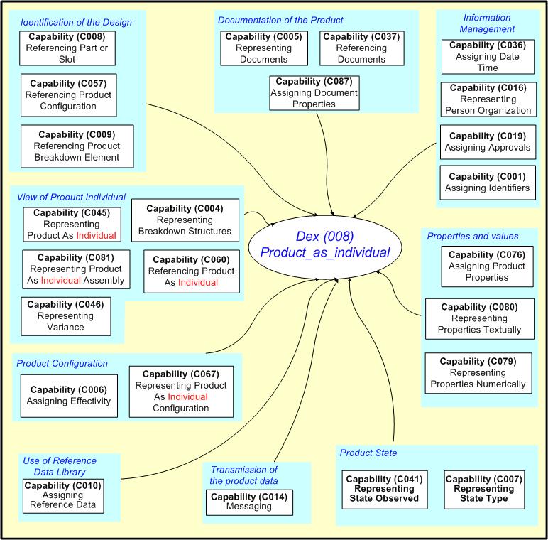
NOTE The diagram above illustrates those capabilities that have a bearing upon the definition of the product to be supported. They are collected into functional groups which relate the capabilities within. The diagram does not show the relationships between the capabilities within or across these functional groups. Each capability shows how they use others in an overview diagram within the Information Model section at the beginning of each capability.
NOTE A part may be refered to through it's design by the EXPRESS entity Part, though the actual occurence of a version of the product may also be referenced instead, as represented (for example,) by the EXPRESS entity Product_as_realized.
Managing information relies upon identification and this is a recurring key concept within PLCS and this Dex.
An Identification_assignment (see capability C001: assigning_identifiers for details), is the assignment of an identifier to product or activity data. Such items are identified by creating an identifier that is unique in the context of an organization (or enterprise) and assigning the identifier to the item. Examples of items to be identified include; Parts, Tasks and Organizations.
The approach adopted is compatible with that provided in the DOD Memorandum "The Department of Defence Guide to Uniquely Identifying Items, Version 1.3" dated November 25th, 2003.
EXAMPLE Identifiers can be Serial Numbers, Part Numbers, Nato Stock Numbers, CAGE Codes etc..
EXAMPLE Organizations that provide the context for an identifier include; Prime Contractor, Design Owner, MOD, Catalogue Owner.
PLCS uses a general approach to identification that comprises the following four key assignments;
An approval is an action by means of which a product or activity or other item is agreed to or officially confirmed as acceptable or satisfactory by a person or organization. See capability C019: assigning_approvals for details.
EXAMPLE A product design might be approved by a customer prior to the commencement of manufacture.
In basic approvals, only one signature or authorization is required. In complex approvals, a series of authorizations may be required for a single approval with a particular status, or a cycle of coordinated approvals that vary in status. Moreover, a single approval may apply to a number of different items. In the case of an approval that applies to a number of items, the assignment of the approval may have a single role or multiple roles.
EXAMPLE An example of a basic approval might be the authorizing of a part design by an individual on a certain date.
EXAMPLE An example of a complex approval with a multiple approval statuses might be an approval cycle where provisional approval is required from a subordinate before an item may be considered for final approval by a superior.
EXAMPLE An example of a complex approval where an approval applies to a number of items might be the authorization of a series of sub-contracts for a sub-assembly designs on the same day.
Approvals are established through the creation of Approval objects and related to other constructs using Approval_assignment objects. Persons and or organizations are related to Approval objects using Approving_person_organization objects. Relationships between Approval objects are established by means of Approval_relationship objects.
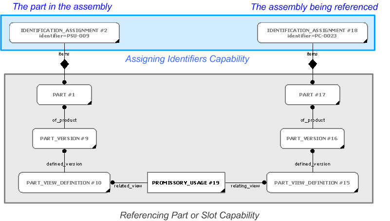
The design of the artefact needs to be able to be identified. This is achieved through referencing the product structure design. The use of a reference assumes that the receiver of the information already has the information that represents the entity being referenced. These references can be broken down into several aspects:
The mechanisms for defining these are outlined in the figure below and detailed in referencing_part_or_slot![]() Error C1: Capability referencing_part_or_slot not in dex_index.xml
Error C1: Capability referencing_part_or_slot not in dex_index.xml
.
Where the design has yet to be provided, product_breakdown_for_support gives the functionality and guidance to generate this.
A reference to a products' parts;
The simplest case of referencing a Part or
Error ER-7: The express_ref linkend
attachment_slot:arm:Attachment_slot_arm.Slot
is incorrectly specified.
The entity does not exist.
Note linkend is case sensitive.
Slot is done by its identifier and version only,
without any further information about the context such as a configuration, a product breakdown etc.
A Part or
Error ER-7: The express_ref linkend
attachment_slot:arm:Attachment_slot_arm.Slot
is incorrectly specified.
The entity does not exist.
Note linkend is case sensitive.
Slot is basically referenced by its identifier along
with the necessary context information. The way a
Part or
Error ER-7: The express_ref linkend
attachment_slot:arm:Attachment_slot_arm.Slot
is incorrectly specified.
The entity does not exist.
Note linkend is case sensitive.
Slot is identified is
described in the in the capabilities C002: representing_parts and
C003: representing_assembly_structure respectively.
In these cases the Part or
Error ER-7: The express_ref linkend
attachment_slot:arm:Attachment_slot_arm.Slot
is incorrectly specified.
The entity does not exist.
Note linkend is case sensitive.
Slot is referenced by it's identifier
(Identification_assignment)
along with the identifier context information, such as the person or organization that assigned the identifier
(Organization_or_person_in_organization_assignment)
and the type of identifier that is being referenced
(Classification_assignment
and External_class) as described in the
C001: assigning_identifiers capability.
Referencing a
Part_version or
Error ER-7: The express_ref linkend
attachment_slot:arm:Attachment_slot_arm.Slot_version
is incorrectly specified.
The entity does not exist.
Note linkend is case sensitive.
Slot_version is done in the same way as
referencing a Part or
Error ER-7: The express_ref linkend
attachment_slot:arm:Attachment_slot_arm.Slot
is incorrectly specified.
The entity does not exist.
Note linkend is case sensitive.
Slot with the addition of the version identification.
The way a Part_version or
Error ER-7: The express_ref linkend
attachment_slot:arm:Attachment_slot_arm.Slot_version
is incorrectly specified.
The entity does not exist.
Note linkend is case sensitive.
Slot_version is identifed is described in the
capabilities C002: representing_parts and
C003: representing_assembly_structure respectively.
However, if the context of the Part or
Error ER-7: The express_ref linkend
attachment_slot:arm:Attachment_slot_arm.Slot
is incorrectly specified.
The entity does not exist.
Note linkend is case sensitive.
Slot is essential, this capability also allows for
the inclusion of the following contexts in which a part or slot can be uniquely identified:
A reference to the products' design configuration;
Complex products can often be configured to perform different roles or configured with different options. Often this is for different markets. For example, a PC can be configured with a power supply rated for 110V or 250V (targeted towards USA and Europe respectively).
Configuration identification in the PLCS Schema is the identification of product concepts and their associated configurations, the composition of which is to be managed. If a configuration of a product concept is implemented by a certain design, i.e., a particular part version, this version can be associated with the configuration and managed using configuration effectivity.
To reference a product configuration requires it's identifier (Identification_assignment) together with the information about the person or organization that assigned the identifier (Organization_or_person_in_organization_assignment) and the type of identifier that is being referenced (Classification_assignment and External_class). Detailed information on how to assign identifiers to a Product_configuration is described in the in the C063: representing_product_configuration capability.
In order to uniquely reference a Product_configuration there also has to be information about the Part_version or Part_view_definition that Product_configuration is related to. This relationship is established via the Item_design_association.
Referencing a part or slot within a design configuration
The Part or
Error ER-7: The express_ref linkend
attachment_slot:arm:Attachment_slot_arm.Slot
is incorrectly specified.
The entity does not exist.
Note linkend is case sensitive.
Slot should be identified as described above.
A relationship from the Part or
Error ER-7: The express_ref linkend
attachment_slot:arm:Attachment_slot_arm.Slot
is incorrectly specified.
The entity does not exist.
Note linkend is case sensitive.
Slot to a
Product_configuration is established via
View_definition_usage
(or any of its subtypes) and
Item_usage_effectivity to
the Item_design_association representing the
the relationship between the referenced
Product_configuration and its associated
Part_version or
Part_view_definition.
The way a
Product_configuration
is refenced is described in the referencing_product_configuration![]() Error C1: Capability referencing_product_configuration not in dex_index.xml
Error C1: Capability referencing_product_configuration not in dex_index.xml
capability.
NOTE The View_definition_usage inherited attribute relating_view is ignored in the example given in figure 3.
A reference to a part or slot in an assembly design definition;
The assembly definition is represented using explicit hierarchical product structures, usually a subtype of Assembly_component_relationship, such as Next_assembly_usage, for example, to represent assemblies and the constituents (Parts) of those assemblies. This explicit part structure corresponds to the traditional engineering and manufacturing bill of material (BOM) indentured parts list. Relationships between Part_view_definitions are the principle elements used to structure an explicit design assembly configuration. The relationship itself represents a specific usage of the constituent design definition within the immediate parent assembly definition.
An assembly definition is basically referenced by its identifier along with the necessary context information. The way assemblies are identified is provided within C003: representing_assembly_structure.
The simplest case of referencing an assembly is achieved by it's identifier and associated context (if required).
The identifier will most likely be able to be used by itself, but to obtain a unique identification, the identifier, the owning organization and the date/time of the identification are required (as explained within C001: assigning_identifiers).
Further context of the assembly is provided through filtering the relevant subtypes;
Further details of referencing assembly structures is provided in C003: representing_assembly_structure.
Referencing a part or slot in an assembly
The Part or
Error ER-7: The express_ref linkend
attachment_slot:arm:Attachment_slot_arm.Slot
is incorrectly specified.
The entity does not exist.
Note linkend is case sensitive.
Slot should be identified as described above.
A relationship from the Part or
Error ER-7: The express_ref linkend
attachment_slot:arm:Attachment_slot_arm.Slot
is incorrectly specified.
The entity does not exist.
Note linkend is case sensitive.
Slot to the assembly is established via
Assembly_component_relationship (or any of its subtypes
Next_assembly_usage,
Promissory_usage
or Component_upper_level_identification).
NOTE Depending on which Assembly_component_relationship is being used it might be necessary to iterate this step.
The parent Part (including the Part_version and Part_view_definition) is referenced by it's identifier as described in the C001: assigning_identifiers capability.
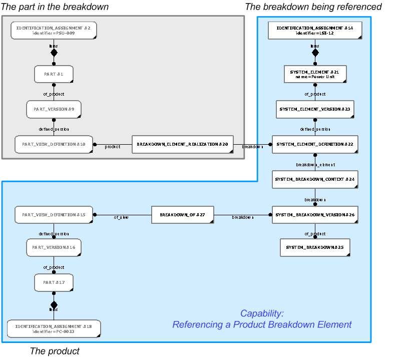
A reference to an element within one of the product's various (design) breakdown views;
Within the support solution, it may be necessary to reference an element within a breakdown view of the design. The breakdown element could be part of a functional, physical, system, zonal or hybrid breakdown.
A breakdown is a partitioning of a product into a set of related elements to support engineering, analysis and other activities that may be performed in relation to the product. These breakdowns are explicit, parent-child views that comprise the product elements.
A product breakdown element is represented in the model as a Breakdown_element or any of its subtypes; Functional_element, Physical_element, System_element, or Zone_element.
A Breakdown_element (or one of its subtypes) may be referenced by its identifier. This identifier should be assigned in accordance with the capability C001: assigning_identifiers.
However, just providing a breakdown element identification does not guarantee a unique entry in e.g. a database system. In order to uniquely reference a breakdown element one also has to provide the context in which the breakdown element can be uniquely identified. This context have to include information about:
The detailed approach to this referencing mechanism is defined within capability referencing_product_breakdown_element![]() Error C1: Capability referencing_product_breakdown_element not in dex_index.xml
Error C1: Capability referencing_product_breakdown_element not in dex_index.xml
.
Referencing a part or slot in a breakdown
A relationship from the Part or
Error ER-7: The express_ref linkend
attachment_slot:arm:Attachment_slot_arm.Slot
is incorrectly specified.
The entity does not exist.
Note linkend is case sensitive.
Slot to a breakdown is established using
Breakdown_element_realization. A reference the identification of
breakdown element is established using the capability referencing_product_breakdown_element![]() Error C1: Capability referencing_product_breakdown_element not in dex_index.xml
Error C1: Capability referencing_product_breakdown_element not in dex_index.xml
.
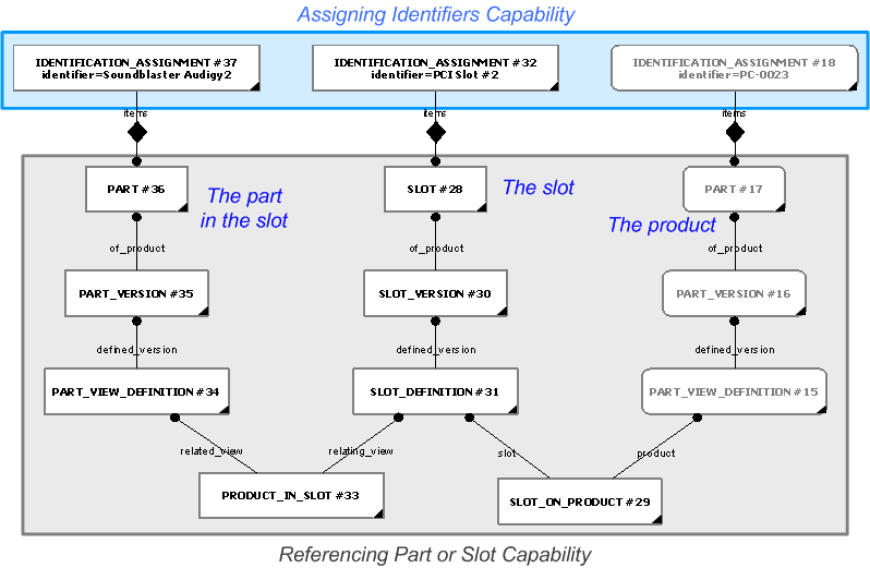
Applying a reference to a part in a slot or slot on a product respectively
A relationship from the referenced
Part to a
Error ER-7: The express_ref linkend
attachment_slot:arm:Attachment_slot_arm.Slot
is incorrectly specified.
The entity does not exist.
Note linkend is case sensitive.
Slot is established via
Error ER-7: The express_ref linkend
attachment_slot:arm:Attachment_slot_arm.Product_in_slot
is incorrectly specified.
The entity does not exist.
Note linkend is case sensitive.
Product_in_slot.
A relationship from the referenced
Error ER-7: The express_ref linkend
attachment_slot:arm:Attachment_slot_arm.Slot
is incorrectly specified.
The entity does not exist.
Note linkend is case sensitive.
Slot to a
Part
is established via
Error ER-7: The express_ref linkend
attachment_slot:arm:Attachment_slot_arm.Slot_on_product
is incorrectly specified.
The entity does not exist.
Note linkend is case sensitive.
Slot_on_product
How a part or slot is referenced repectively, is described in the sections above.
Summary of the Identification of the Design
This section just brings together the previous sections into one area to provide a view of how all the above requirements fit together.
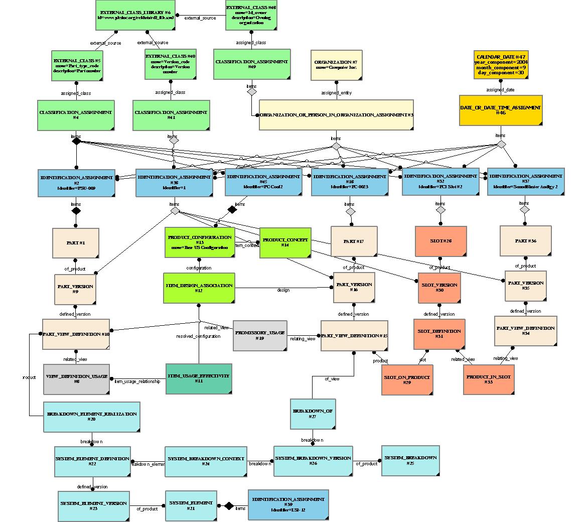
Representing the product structure can be broken down into several aspects:
The representation of the individual product;
The Product_as_individual is a generic term given by PLCS to a product which is in the process of being realized and becoming an artefact rather than the subject of a design.
The Product_as_individual is conceived, designed, planned, fabricated or acquired, assembled, is in-service, retires, and is destroyed, recycled, or discarded. During its life cycle, almost anything about it may change:
The representation of a Product_as_individual, defines the actual occurrence of a Part whether it be designed to be independent or a component of a larger product or assembly. Individuals need to be identified because, through life, they may need to be replaced. For example, due to wear, life expectancy, failure rate, or part alternatives. They may also need to be removed or substituted for other parts through mission requirements, upgrades or due to variants from redesign or reconfiguration.
Without adequate identification, the owner cannot be certain of the configuration of a product, that correct spares are available, that timely maintenence is being carried out, or that the product will fulfill it's functional requirements.
Therefore, each Product_as_individual must be able to be uniquely identified so that it's usage in all Product can be recorded across both versions and variations of those products.
With adequate identification, the usual operations of the product might then be supported, for example, regular maintenance, condition based maintenance, usage reporting, failure reporting, part changes, function changes, replacements and the upkeep to both the product and the APSI can be enabled.
The AP239 approach to representing individuals has been detailed in capability representing_product_as_realized![]() Error C1: Capability representing_product_as_realized not in dex_index.xml
Error C1: Capability representing_product_as_realized not in dex_index.xml
and comprises the following steps;
Representation and Identification of an Individual
The capability representing_product_as_realized![]() Error C1: Capability representing_product_as_realized not in dex_index.xml
Error C1: Capability representing_product_as_realized not in dex_index.xml
(soon to be representing_product_as_individual) describes the representation of describes the representation of Product_as_individual.
The Product_as_individual is represented by two distinct entities in PLCS. The representation, identification and contexts of these are described below;
The part number is assigned to the
Part
by an instance of
Identification_assignment
which is classified as
[Part_code]![]() Error RDL1: The class Part_code does not exist in RDL at URI urn:plcs:rdl:std. Check the dexlib/data/refdata/rdl_index.xml
Error RDL1: The class Part_code does not exist in RDL at URI urn:plcs:rdl:std. Check the dexlib/data/refdata/rdl_index.xml
.
If the proposed artefact has been made from a version of the
design then it maybe related to the version
(Part_version)
by the relation entity
Product_design_to_individual.
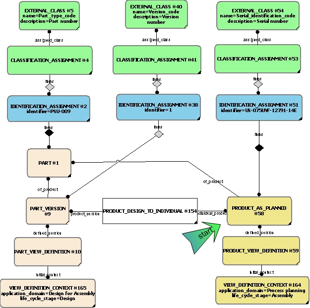
If the artefact is a result of the product as planned then it maybe related to the relevant version of the Product_as_planned by the relation entity Product_planned_to_realized.
If the artefact has been made from a version of the design then it may also be related to the version (Part_version) by the relation entity Product_design_to_individual.
The part number is assigned to the
Part
by an instance of
Identification_assignment
which is classified as
[Part_code]![]() Error RDL1: The class Part_code does not exist in RDL at URI urn:plcs:rdl:std. Check the dexlib/data/refdata/rdl_index.xml
Error RDL1: The class Part_code does not exist in RDL at URI urn:plcs:rdl:std. Check the dexlib/data/refdata/rdl_index.xml
.

A more detailed description of the representation of individuals is provided in the capability referencing_product_as_realized![]() Error C1: Capability referencing_product_as_realized not in dex_index.xml
Error C1: Capability referencing_product_as_realized not in dex_index.xml
(soon to become representing_product_as_individual).
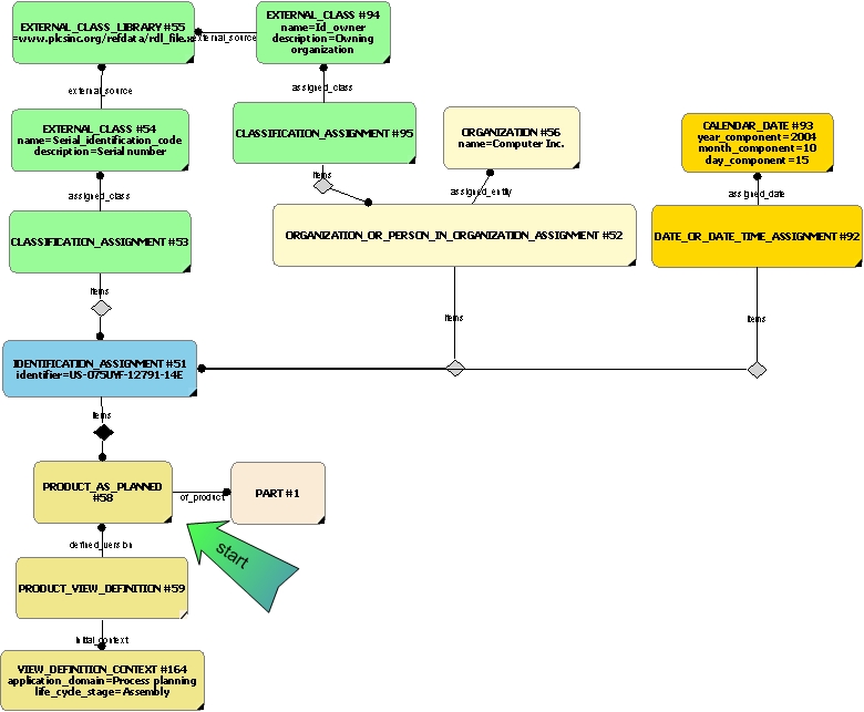
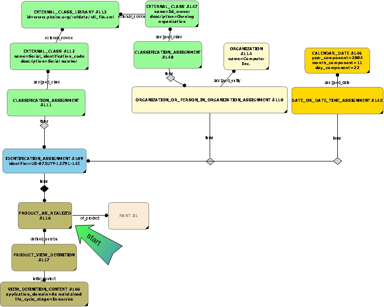
Referencing a Product as Individual
To refer to product individuals that have already been exchanged, only the individual and it's associated identification entities
are required. This is depicted in Figure 1 for Product_as_planned and in Figure 3 for Product_as_realized individuals. It may not always be necessary to use the organization and/or date assigned, though for unique identification
is will provide greater assurance. However, an additional classification of the individual is required to be set to the string
value 'reference'. A description of the referencing of realized individuals is provided in capability referencing_product_as_realized![]() Error C1: Capability referencing_product_as_realized not in dex_index.xml
Error C1: Capability referencing_product_as_realized not in dex_index.xml
(soon to become referencing_product_as_individual).
The representation of the individual product's configuration definition
The Dex supports the definition of product concepts, which define products from a market or customer oriented viewpoint. As they are offered to the customers, these product concepts often define conceptual 'product models' which are available or delivered to the customer in different configurations or variations.
Configuration identification in this Dex is the identification of product concepts and their associated configurations, the composition of which is to be managed. If a configuration of a product concept is implemented by a certain design, or individual i.e., a particular part version or product as realized, this version can be associated with the configuration and managed using configuration effectivity.
NOTE Explicit representation of the configurations of a product concept is suitable for management of design as-planned manufacturing configurations, the traditional BOM inputs to manufacturing resource planning. These explicit configurations may also be suitable for management of other activities 'downstream' from the design phase, such as as-built and as-maintained configurations.
The representation of product configuration identification is described in the capability C063: representing_product_configuration and whilst closely related, the representation of configuration composition management is described in the capability C006: assigning_effectivity.
To refer to an individual's product configuration that may have already been exchanged, requires the identification of the Product_configuration and identification details of the the individual product and version linked to the configuration by the Item_design_association. An additional classification of the these two main entities is required and should be set to the string value 'reference' so that they are treated correctly.
Representing the Product As Individual Configuration
The products that are sold by an organization to its customers are often defined as variations or configurations of a common product model, referred to as product concept. This product concept is defined in a market context and can be seen as a logical container for all of its variations. In the PLCS Schema, product concept identification is the representation of these product concepts with their related market context.
A Product_concept represents a conceptual idea of a class of similar products that are offered to a Market. No design or manufacturing related product data can be attached to the Product_concept directly. The members of that product class are the different configurations that are available for the Product_concept. Within the PLCS Schema, these configurations are defined explicitly as Product_configurations, each of them being potentially related to Product_as_individuals that implement the particular configuration. A Product_concept will usually be referenced by at least one associated Product_configuration specifying a particular configuration. See the capability representing_product_as_realized_configuration![]() Error C1: Capability representing_product_as_realized_configuration not in dex_index.xml
Error C1: Capability representing_product_as_realized_configuration not in dex_index.xml
(to become representing_product_as_individual_configuration) for more details.
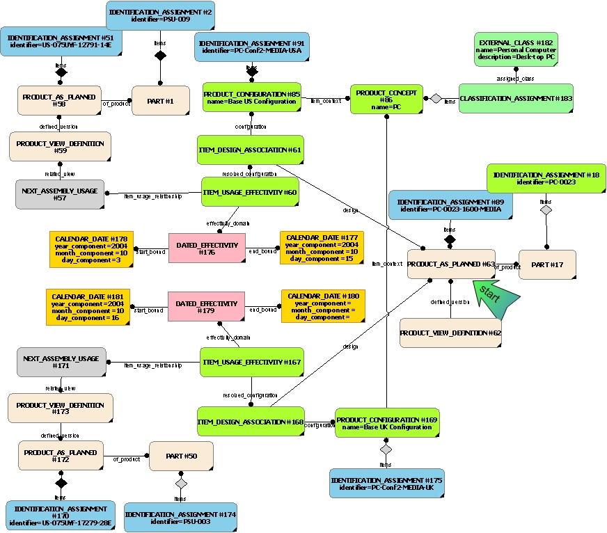
EXAMPLE There might be a manufacturer of a personal computer system which is marketed to both the US and the European markets. The design may allow for two configurations; one for the US and one for Europe. The configuration is only different in that a different power supply is used depending upon which market the PC is assembled for. Another manufacturer may have a switchable PSU and may therefore, only need one configuration.
NOTE The relating_view of the next assembly usage entity is not shown - see the section on assembly below. The additional classification as a reference is not shown but will be coverd in a later section.
NOTE The identification of the Product_concept is provided in more detail in the C001: assigning_identifiers capability.
NOTE There might be several levels of product concepts defined in a company. The description of product concept structures and relationships is not supported by the current PLCS Schema, nor this Dex. It is therefore recommended to instantiate the lowest level product_concept that is offered to the customer.
The Product_configuration defines a manufacturable end item, or something that is conceived and expected as such. The association between a Product_configuration and a corresponding Product_as_individual (such as Product_as_realized or Product_as_planned) is established using an instance of Item_design_association. The valid use of component parts for planned units of manufacturing of a particular Product_configuration may be specified using configuration effectivity (see capability C006: assigning_effectivity) for details.
When a product is designed, it is first represented as a Product_concept. For example, a new bicycle will be initially represented as a Product_concept. Then a number of possible configurations of the product are identified and represented by a Product_configuration. For example, there may be many wheel designs, but two sets are chosen to accompany two product configurations of the bicycle concept. An ordinary bike (with normal wheels), then a racing bicycle fitted with racing wheels.
Before manufacture it will be represented by an assembly structure (represented by Product_as_planned) that can be configured in any of the two configuration options. See figure above for example). The possible configurations, represented by Product_configuration, are related to the Product_as_planned by Item_design_association.
Once the product has been manufactured it will be represented by another assembly structure (represented by Product_as_realized) that can be configured in any of the two configuration options. The possible configurations, represented by Product_configuration, are related to the Product_as_realized by Item_design_association.
The assembly structure represents all the valid possible assemblies for those configurations. These are represented by instances of Next_assembly_usage relating the views (Product_view_definition") of the components of the bicycle (instances of Product_as_planned or Product_as_realized - depending upon whether pre or post production).
The representation of product configuration identification is described in the capability C063: representing_product_configuration, (soon to become representing_product_as_individual_configuration) and whilst closely related, the representation of configuration composition management is described in the capability C006: assigning_effectivity.
A more detailed description of the representation of individuals is provided in the capability representing_product_as_realized_configuration![]() Error C1: Capability representing_product_as_realized_configuration not in dex_index.xml
Error C1: Capability representing_product_as_realized_configuration not in dex_index.xml
(soon to become representing_product_as_individual_configuration).
Referencing an Individual within a Product Configuration
To refer to a product individual within a configuration, both the individual and the configuration need to be identified.
However, an additional classification of the individual is required to be set to the string value 'reference'. A description
of the referencing a product configuration is provided in capability referencing_product_configuration![]() Error C1: Capability referencing_product_configuration not in dex_index.xml
Error C1: Capability referencing_product_configuration not in dex_index.xml
.
A relationship from the Product_as_planned or
Product_as_realized to a
Product_configuration is established via
View_definition_usage
(or any of its subtypes - e.g. next assembly usage) and
Item_usage_effectivity to
the Item_design_association representing the
the relationship between the referenced
Product_configuration and its associated
Product_version(such as a Product_as_planned or Product_as_realized) or a
Product_view_definition.
The way a
Product_configuration
is referenced is described in the referencing_product_configuration![]() Error C1: Capability referencing_product_configuration not in dex_index.xml
Error C1: Capability referencing_product_configuration not in dex_index.xml
capability.
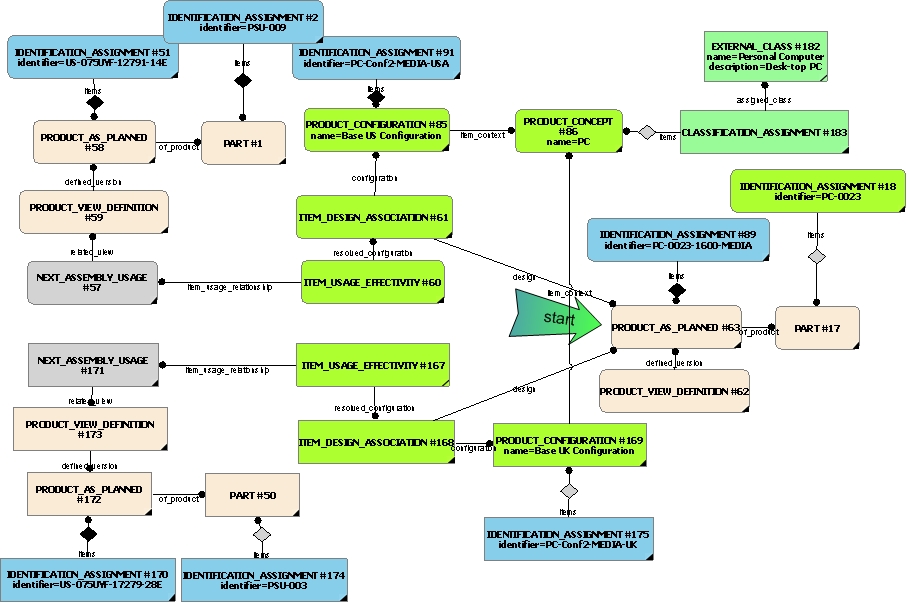
The following figure shows the references to a configuration of planned individuals.
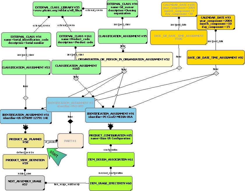
NOTE The two key entities are the product as planned and the product configuration instances along with their identification and classification. The organization and date time assignment information however, is required for unique identification. Also note that the identification and classification of the associated design part was carried out at an earlier date as shown by the date time assignment of #106.
NOTE That it is reasonable to assume that given the two references above, that the host system should be capable of tracing the link(s) between them to establish that the individual is part of the configuration.
NOTE To Tim - if this is not the case then all those entity instances between the two refered to above need to be provided. In theory, there may be many product view definitions that point to the part (#58 for example), and in addition there may be a number of view_definition_usage instances that also link to the configuration. Question being - is this important if only trying to identify that the individual is part of a configuration? Probably not - but worth point out perhaps?
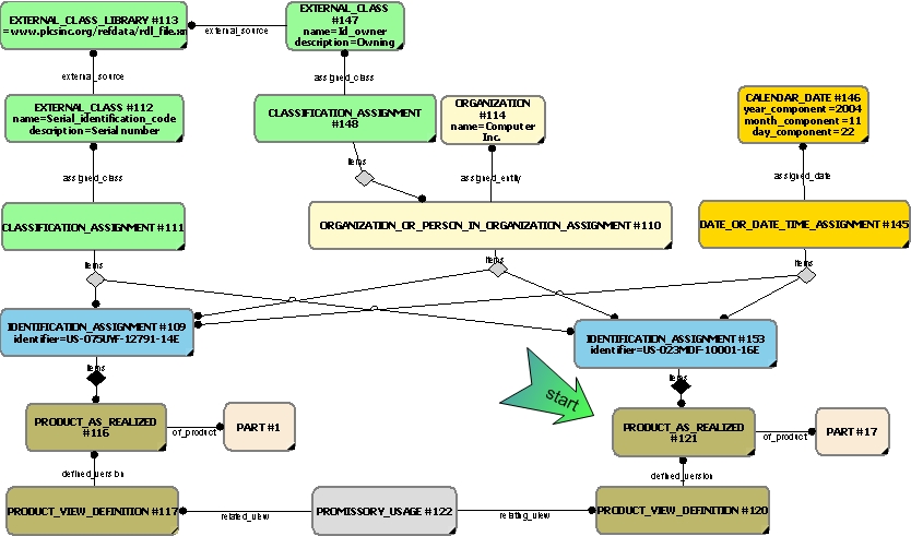
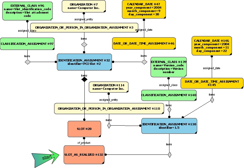
The following figure shows the instances required to reference a specific version of a realized individual within a configuration
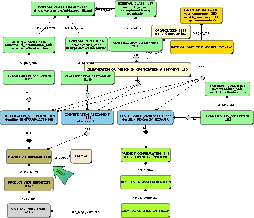
NOTE The two key entities are the product as realized and the product configuration instances along with their identification and classification. In this case, however, we are also referencing a specific version of the realized individual (denoted by #138). The organization and date time assignment information however, is required for unique identification.
NOTE That it is reasonable to assume that given the two references above, that the host system should be capable of tracing the link(s) between them to establish that the individual is part of the configuration.
NOTE To Tim - if this is not the case then all those entity instances between the two refered to above need to be provided. In theory, there may be many product view definitions that point to the part (#117 for example), and in addition there may be a number of view_definition_usage instances that also link to the configuration. Question being - is this important if only trying to identify that the individual is part of a configuration? Probably not - but worth point out perhaps?
Effectivity is a key concept to control the valid use of product data. This Dex supports the association of effectivity information
to different types of product data through the Item_usage_effectivity entity. This entity represents a tuple of; a resolved_configuration (an instance of Item_design_association - see above or representing_product_as_realized_configuration![]() Error C1: Capability representing_product_as_realized_configuration not in dex_index.xml
Error C1: Capability representing_product_as_realized_configuration not in dex_index.xml
), an effectivity_domain (an instance of a type of Effectivity), and an item_usage_relationship (i.e. an instance of a type of View_definition_usage, such as Next_assembly_usage (see above or representing_product_as_realized_assembly![]() Error C1: Capability representing_product_as_realized_assembly not in dex_index.xml
Error C1: Capability representing_product_as_realized_assembly not in dex_index.xml
).
The Effectivity entity supports the specification of a domain of applicability for product data. Effectivity is a generic concept defining the valid use of the product data to which the effectivity is assigned.
The subtypes of Effectivity include;
These subtypes restrict the domain of applicability of the associated product data to a date range, a particular lot or serial number range, or to a time interval respectively.
Hence, an instance of Item_usage_effectivity may associate a Product_configuration (through the Item_design_association), and a definition of the assembly (Next_assembly_usage through View_definition_usage) with a type of Effectivity.
Configuration effectivity allows attachment of effectivity information to occurrences of component parts in the context of a particular configuration item. This enables the specification of the valid use of a part occurrence in the context defined for a particular product configuration. This controls the constituent parts that are planned to be used for manufacturing end items of a particular product configuration within a dated time period or for a certain lot or serial number range of the end items.
While configuration effectivity (as described above) is used to define the planned usage of components in the context of a particular product configuration, the Dex also allows assignment of general validity periods to product data that control the usage of these product data independent of any particular life cycle or context.
The validity period of Effectivity may be applied to different types of product data, potentially specifying an additional role in which the effectivity is assigned. The Effectivity_assignment entity defines a general mechanism to associate a general period of validity to some product data or activity.
The entity Effectivity_assignment refers to one or more items (instances) of product data to which the validity period is assigned. The types of product data to which an effectivity may be assigned are defined in the effectivity_item select type.
NOTE The assignment of effectivities is often done during the approval process, i.e, when releasing product data for the next stage of the development process, it gets effectivity information assigned to determine when and in which context these product data may be used.
The representation of the individual product's assembly definition
The assembly definition is represented using explicit hierarchical product structures (e.g. Next_assembly_usage) representing assemblies and the constituents of those assemblies. In the design stage this would involve consituents such as Parts, but in the process planning stage and as-built/in-service stages these are represented by Product_as_individuals (such as a Product_as_planned or Product_as_realized). Relationships between Product_view_definitions are the principle elements used to structure an explicit assembly configuration. The relationship itself represents a specific usage of the constituent definition within the immediate parent assembly definition. Mechanisms to represent quantity associated with this Assembly_component_relationship usage are not required at this stage since there is a specific occurrence for each individual used. Thus the quantity is the sum of the individuals provided.
Using Product_as_individuals (a type of Product_version), rather than a Parts provides the capability to identify and track the specific usage of component definitions in an assembly. This enforces a typcial tree-like hierarchy of instances through the normal parent-child relationships rather than the frequent graph-like structures that are possible at the design stage.
Hence different view definitions (Product_view_definitions) of the same Product_as_individual may participate in different explicit product structures. For example, as-built, in-service and as-maintained views of the same Product_as_realized may be different. This is in addition to differences with the planned assembly and manufacture structures using Product_as_planned instances.
In addition to these hierarchical assembly structures discussed above, capability representing_product_as_realized_assembly![]() Error C1: Capability representing_product_as_realized_assembly not in dex_index.xml
Error C1: Capability representing_product_as_realized_assembly not in dex_index.xml
supports relationships between parts to characterize explicit alternates and substitutes for the assembly.
The Referencing of an Individual within an Assembly
The two figures below show how an individual can be referenced in the context of an assembly. This requires the identification
of both the assembly and the individual. However, to clarify that these are only references rather than aother assembly being
defined, an additional classification of the individual is required to be set to the string value 'reference'. A description
of the referencing an assembly is provided in capability referencing_part_or_slot![]() Error C1: Capability referencing_part_or_slot not in dex_index.xml
Error C1: Capability referencing_part_or_slot not in dex_index.xml
.
The reference is a two-stage process. The first is to identify the root Product_as_individual which represents the top root node of the assembly being referenced. This may be a Product_as_planned or Product_as_realized. This individual will be the defined_version of a Product_view_definition instance.
The second stage is to trace the assembly hierarchy to locate the individual. This can be achieved through an instance of type Assembly_component_relationship (such as Next_assembly_usage, Promissory_usage or Component_upper_level_identification), which relates two instances of Product_view_definition together. The relating_view identifies the parent in the assembly, whereas the related_view identifies the child node in the assembly. The Product_view_definition of the child node has a defined_version which may be the Product_as_individual sought.
NOTE Depending on which Assembly_component_relationship is being used and since the Product_view_definition of the child node may itself be a parent in another parent-child relationship, this stage may need to be re-iterated in order to recurse down to the level in the hierarchy where the individual sought is located.
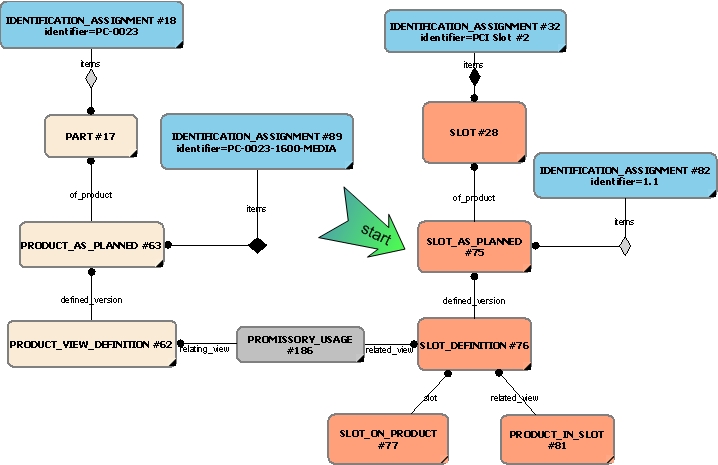
The following figure shows the reference of a planned individual within a simple, planned (promissory) assembly.
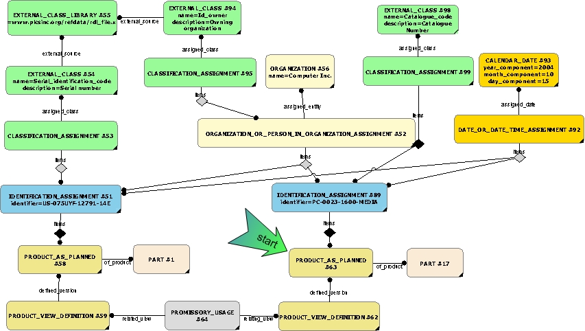
The following figure shows the reference of a realized individual within a simple, realized (promissory) assembly.
The use of Slots in an Assembly
A slot represents the position in which a part is or can be attached to an assembly, when it is necessary to record the history of usage of that slot. It defines the concepts required to build the relationships which provide the structure for representing slots.
EXAMPLE A ship has four engines each attached at a mounting point in an engine room. These mounting points each has an associated slot, which are identified as slot 1, slot 2, slot 3, and slot 4. In normal usage only two main engines are are operating, the remaining two provide an operating enhancement if all four operate or a backup for the two main engines. The attached engines are tracked against their respective slots. If the ship does not have all of its engines installed, one or more slots are empty. An empty slot is subject to a different maintenance regime than an installed engine.
Error ER-7: The express_ref linkend
attachment_slot:arm:Attachment_slot_arm.Slot
is incorrectly specified.
The entity does not exist.
Note linkend is case sensitive.
Slots are subject to identification requirements as described within capability C001: assigning_identifiers. Hence, the Error ER-7: The express_ref linkend
attachment_slot:arm:Attachment_slot_arm.Slot
is incorrectly specified.
The entity does not exist.
Note linkend is case sensitive.
Slotshould be referenced by an Identification_assignment, which acts as the focus for; a Classification_assignment (and External_class), an Organization_or_person_in_organization_assignment and a Date_or_date_time_assignment. In this respect, the model closely resembles that of Part described within capability C002: representing_parts.
A Error ER-7: The express_ref linkend
attachment_slot:arm:Attachment_slot_arm.Slot
is incorrectly specified.
The entity does not exist.
Note linkend is case sensitive.
Slot may have one or more versions
(Error ER-7: The express_ref linkend
attachment_slot:arm:Attachment_slot_arm.Slot_version
is incorrectly specified.
The entity does not exist.
Note linkend is case sensitive.
Slot_version),
and each may have one or more applicable view definitions
(Error ER-7: The express_ref linkend
attachment_slot:arm:Attachment_slot_arm.Slot_definition
is incorrectly specified.
The entity does not exist.
Note linkend is case sensitive.
Slot_definition).
A Error ER-7: The express_ref linkend
attachment_slot:arm:Attachment_slot_arm.Slot_version
is incorrectly specified.
The entity does not exist.
Note linkend is case sensitive.
Slot_version may exist in the form of a designed slot
(Error ER-7: The express_ref linkend
attachment_slot:arm:Attachment_slot_arm.Slot_design
is incorrectly specified.
The entity does not exist.
Note linkend is case sensitive.
Slot_design),
a planned slot
(Error ER-7: The express_ref linkend
attachment_slot:arm:Attachment_slot_arm.Slot_as_planned
is incorrectly specified.
The entity does not exist.
Note linkend is case sensitive.
Slot_as_planned)
or a realized slot
(Error ER-7: The express_ref linkend
attachment_slot:arm:Attachment_slot_arm.Slot_as_realized
is incorrectly specified.
The entity does not exist.
Note linkend is case sensitive.
Slot_as_realized).
These versions correspond to the same PLCS approach to lifecycle management that are afforded to Parts, Product_as_planned and Product_as_realized described earlier in the busines section. The distinction between design, planned and realized products is also provided
in capability representing_product_as_realized![]() Error C1: Capability representing_product_as_realized not in dex_index.xml
Error C1: Capability representing_product_as_realized not in dex_index.xml
(shortly to become representing_product_as_individual).
Versions are identified through a version code (usually a number) while the original Error ER-7: The express_ref linkend
attachment_slot:arm:Attachment_slot_arm.Slot
is incorrectly specified.
The entity does not exist.
Note linkend is case sensitive.
Slot can be identified through the Error ER-7: The express_ref linkend
attachment_slot:arm:Attachment_slot_arm.Slot_version
is incorrectly specified.
The entity does not exist.
Note linkend is case sensitive.
Slot_version's Error ER-6: The express_ref linkend
attachment_slot:arm:Attachment_slot_arm.Slot_version.of_product
is incorrectly specified. The attribute does not exist.
Note linkend is case sensitive.
of_product attribute.
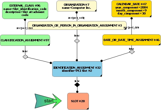
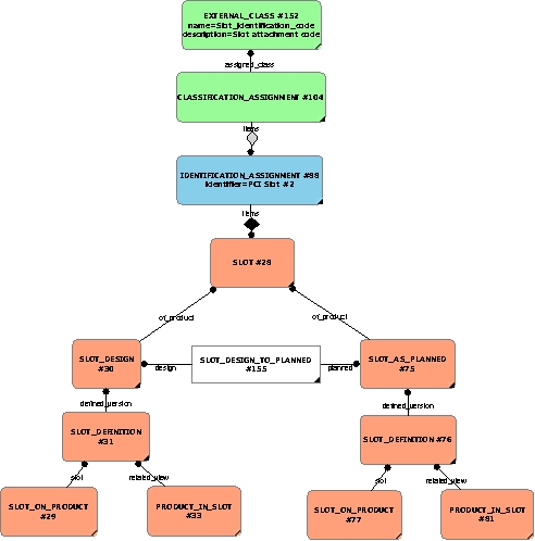
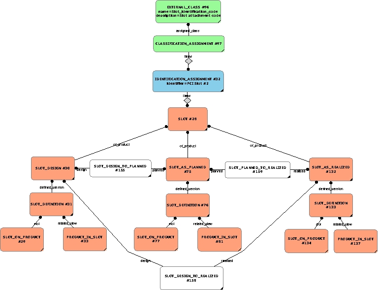
The following figures show the representation of these three types of versions.
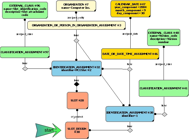
NOTE Both slot and slot design are shown having the same date/time for the assignments. It is likely the the slot is defined at the time of representing the design.
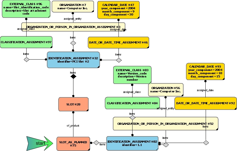
NOTE Both slot and slot as planned are shown having different date/time for the assignments. It is likely that the date of design is earlier than that of the process plan.
NOTE Both slot and slot as realized are shown having different date/time for the assignments. It is likely that the date of design and planned versions is earlier than that of the realized/as-built.
The relationships Error ER-7: The express_ref linkend
attachment_slot:arm:Attachment_slot_arm.Slot_on_product
is incorrectly specified.
The entity does not exist.
Note linkend is case sensitive.
Slot_on_product
and Error ER-7: The express_ref linkend
attachment_slot:arm:Attachment_slot_arm.Product_in_slot
is incorrectly specified.
The entity does not exist.
Note linkend is case sensitive.
Product_in_slot
identify the slot attached to a product and which part has been fitted to the slot, respectively.
The Error ER-7: The express_ref linkend
attachment_slot:arm:Attachment_slot_arm.Slot_on_product
is incorrectly specified.
The entity does not exist.
Note linkend is case sensitive.
Slot_on_product relates a Error ER-6: The express_ref linkend
attachment_slot:arm:Attachment_slot_arm.Slot_on_product.slot
is incorrectly specified. The attribute does not exist.
Note linkend is case sensitive.
slot on one hand to a Error ER-6: The express_ref linkend
attachment_slot:arm:Attachment_slot_arm.Slot_on_product.product
is incorrectly specified. The attribute does not exist.
Note linkend is case sensitive.
product on the other. The former links to the Error ER-7: The express_ref linkend
attachment_slot:arm:Attachment_slot_arm.Slot_definition
is incorrectly specified.
The entity does not exist.
Note linkend is case sensitive.
Slot_definition described below, while the other should link to a type of Product_view_definition (or a subtype such as Part_view_definition).
A Error ER-7: The express_ref linkend
attachment_slot:arm:Attachment_slot_arm.Slot_definition
is incorrectly specified.
The entity does not exist.
Note linkend is case sensitive.
Slot_definition is attached to a product through the relationship entity Error ER-7: The express_ref linkend
attachment_slot:arm:Attachment_slot_arm.Slot_on_product
is incorrectly specified.
The entity does not exist.
Note linkend is case sensitive.
Slot_on_product. The Error ER-7: The express_ref linkend
attachment_slot:arm:Attachment_slot_arm.Slot_definition
is incorrectly specified.
The entity does not exist.
Note linkend is case sensitive.
Slot_definition has a Error ER-6: The express_ref linkend
attachment_slot:arm:Attachment_slot_arm.Slot_definition.defined_version
is incorrectly specified. The attribute does not exist.
Note linkend is case sensitive.
defined_version attribute linking the Error ER-7: The express_ref linkend
attachment_slot:arm:Attachment_slot_arm.Slot_version
is incorrectly specified.
The entity does not exist.
Note linkend is case sensitive.
Slot_version. This, in turn, has an attribute Error ER-6: The express_ref linkend
attachment_slot:arm:Attachment_slot_arm.Slot_version.of_product
is incorrectly specified. The attribute does not exist.
Note linkend is case sensitive.
of_product which links to the Error ER-7: The express_ref linkend
attachment_slot:arm:Attachment_slot_arm.Slot
is incorrectly specified.
The entity does not exist.
Note linkend is case sensitive.
Slot.
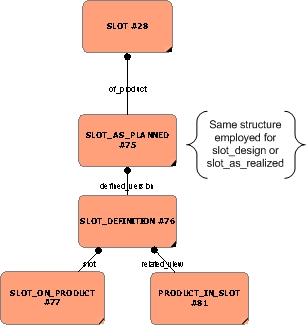
NOTE The same structure of elements are employed to represent both slot_design and slot_as_realized. These are not shown here. See capabiliity representing_slots for more details.
Since an assembly is built from relationships between Product_view_definitions and a Error ER-7: The express_ref linkend
attachment_slot:arm:Attachment_slot_arm.Slot_definition
is incorrectly specified.
The entity does not exist.
Note linkend is case sensitive.
Slot_definition is a subtype of this, there is a mechanism to include Error ER-7: The express_ref linkend
attachment_slot:arm:Attachment_slot_arm.Slot
is incorrectly specified.
The entity does not exist.
Note linkend is case sensitive.
Slots within an assembly.
NOTE A complete assembly is not shown here - only the use of one contruct (promissory_usage) typically used in the representation of an assembly. Next_assembly_usage is another popular building block.
NOTE The slot in this case forms part of a simple assembly (through promissory_usage) and at the same time identifies the parent in the assembly as the product upon which the slot sits. A slot may be defined at any level in the assembly - not just the top level as shown here.
Representing a part or product that occupies a slot makes use of the Error ER-7: The express_ref linkend
attachment_slot:arm:Attachment_slot_arm.Product_in_slot
is incorrectly specified.
The entity does not exist.
Note linkend is case sensitive.
Product_in_slot relationship which links a Error ER-7: The express_ref linkend
attachment_slot:arm:Attachment_slot_arm.Slot_definition
is incorrectly specified.
The entity does not exist.
Note linkend is case sensitive.
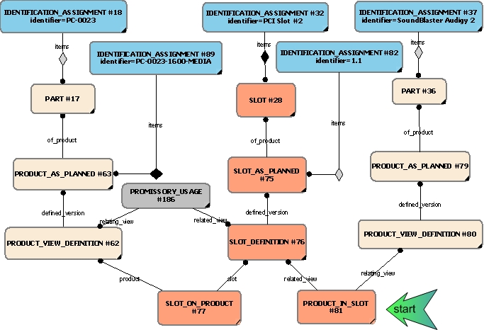
Slot_definition with a Product. The following figure shows the representation of a Soundblaster PC card occupying the slot defined which is part of the
PC assembly. It also shows the use of the Error ER-7: The express_ref linkend
attachment_slot:arm:Attachment_slot_arm.Slot_on_product
is incorrectly specified.
The entity does not exist.
Note linkend is case sensitive.
Slot_on_product which identifies the top-level product on which the Error ER-7: The express_ref linkend
attachment_slot:arm:Attachment_slot_arm.Slot
is incorrectly specified.
The entity does not exist.
Note linkend is case sensitive.
Slot sits.
Management of a Slot through life
If the Error ER-7: The express_ref linkend
attachment_slot:arm:Attachment_slot_arm.Slot_as_planned
is incorrectly specified.
The entity does not exist.
Note linkend is case sensitive.
Slot_as_planned has been produced from a specific Error ER-7: The express_ref linkend
attachment_slot:arm:Attachment_slot_arm.Slot_design
is incorrectly specified.
The entity does not exist.
Note linkend is case sensitive.
Slot_design, then the Error ER-7: The express_ref linkend
attachment_slot:arm:Attachment_slot_arm.Slot_design
is incorrectly specified.
The entity does not exist.
Note linkend is case sensitive.
Slot_design maybe related to the Error ER-7: The express_ref linkend
attachment_slot:arm:Attachment_slot_arm.Slot_as_planned
is incorrectly specified.
The entity does not exist.
Note linkend is case sensitive.
Slot_as_planned by the relation entity Error ER-7: The express_ref linkend
attachment_slot:arm:Attachment_slot_arm.Slot_design_to_planned
is incorrectly specified.
The entity does not exist.
Note linkend is case sensitive.
Slot_design_to_planned.
If the Error ER-7: The express_ref linkend
attachment_slot:arm:Attachment_slot_arm.Slot_as_realized
is incorrectly specified.
The entity does not exist.
Note linkend is case sensitive.
Slot_as_realized has been produced from a specific Error ER-7: The express_ref linkend
attachment_slot:arm:Attachment_slot_arm.Slot_as_planned
is incorrectly specified.
The entity does not exist.
Note linkend is case sensitive.
Slot_as_planned, then the they maybe related by the relation entity Error ER-7: The express_ref linkend
attachment_slot:arm:Attachment_slot_arm.Slot_planned_to_realized
is incorrectly specified.
The entity does not exist.
Note linkend is case sensitive.
Slot_planned_to_realized.
If the Error ER-7: The express_ref linkend
attachment_slot:arm:Attachment_slot_arm.Slot_as_realized
is incorrectly specified.
The entity does not exist.
Note linkend is case sensitive.
Slot_as_realized has been made from a Error ER-7: The express_ref linkend
attachment_slot:arm:Attachment_slot_arm.Slot_design
is incorrectly specified.
The entity does not exist.
Note linkend is case sensitive.
Slot_design then it may also be related to that version of the design by the relation entity Error ER-7: The express_ref linkend
attachment_slot:arm:Attachment_slot_arm.Slot_design_to_realized
is incorrectly specified.
The entity does not exist.
Note linkend is case sensitive.
Slot_design_to_realized.
In cases where it is necessary to identify specific versions, the identification assignment of each should be specified. The figure below shows this.
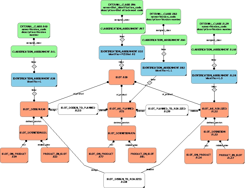
The Referencing of Individual Slots
Referencing slots for the design was provided in an earlier section. The mechanism to refer to Error ER-7: The express_ref linkend
attachment_slot:arm:Attachment_slot_arm.Slot_as_planned
is incorrectly specified.
The entity does not exist.
Note linkend is case sensitive.
Slot_as_planned and Error ER-7: The express_ref linkend
attachment_slot:arm:Attachment_slot_arm.Slot_as_realized
is incorrectly specified.
The entity does not exist.
Note linkend is case sensitive.
Slot_as_realized is the same and is not repeated here.
The representation of breakdowns of individuals;
When defining the support solution, it may be necessary to represent a breakdown view of the product. A breakdown is a partitioning of a product into a set of related elements to support engineering, analysis and other activities that may be performed in relation to the product. These breakdowns are explicit, parent-child views that comprise the product elements.
These views may be represented through a Breakdown (that specifies the representation of various breakdowns of products), or through one of it's subtypes, such as; System_breakdown (for the representation of various breakdowns of a systems), Functional_breakdown (for the representation of various functional breakdowns of products), Physical_breakdown (for the representation of various physical breakdowns of products), Zone_breakdown (for the representation of various zonal breakdowns of products), or through a Hybrid_breakdown (for the representation of various hybrid breakdowns of products).
A product breakdown element is represented in the model as a Breakdown_element or any of its subtypes; Functional_element, Physical_element, System_element, or Zone_element - depending upon the type of breakdown being defined.
These views are complementary to the assembly structure and bill of materials views that are the primary focus for manufacturing (realization) of a product. Breakdowns may be of designs or realized individual products. For any product, more than one breakdown may exist to provide the support solution.
The AP239 PLCS approach to product breakdown (as defined within capability C004: representing_breakdown_structure) comprises the following;
There are a number of aspects to note about the functionality of this model. Firstly, for any product individual (or design), there may be more than one type of breakdown. The second is that each breakdown may have more than one element as a constituent. Thirdly, the various in-built types of breakdowns made explicit by the model (i.e. functional, physical, zone and system), reflect the various life cycle stages applicable to many products, so those defined later in the life cycle will not necessarily be present early on. The model thus, provides the means to represent the product at various phases of the life cycle. This can then be exploited during subsequent phases where for example, physical elements may realize functional ones. Similarly, the physical elements may be realized by the assembly. Thus, since each breakdown may become a structure (tree-like), they may present orthogonal views on the same part or individual. One way to visualise this is as many product trees inter-connecting at various points across a network. However, they all have their own root according to the breakdown defined.
NOTE It is not expected, nor to be assumed that every node in one breakdown will correspond with that of one of more nodes in other breakdowns or assembly definitions. Indeed, the structuring of the information may well be different and should be expected to be so.
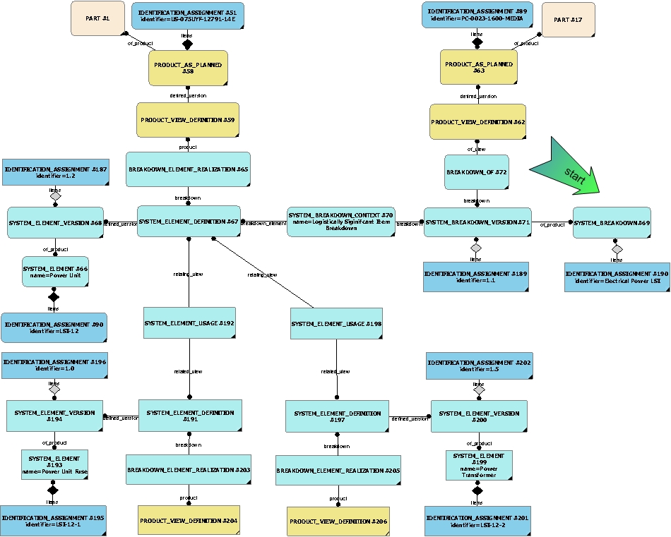
NOTE The breakdown is a type of system breakdown for the electrical power for the PC. The context provided is for logistically significant items and the breakdown shows the PSU broken down into a fuse and a transformer. Identification is applied to system, system version, and to each element and element version. (The cexternal class and class library has been left off for readability. The realization of each definition is shown to be a product view definition of a planned individual (not shown for the fuse or transformer), which is a version of the product designed (part). The system element usage shows that the parent is the PSU with the serial number, whereas the child nodes are the fuse and the transformer.
See capability C004: representing_breakdown_structure for a detailed description on this and the other types of breakdowns.
Referencing a Breakdown Element
A Breakdown_element (or one of its subtypes) shall be referenced by its identifier. This identifier should be assigned in accordance with the capability C001: assigning_identifiers.
However, just providing a breakdown element identification does not guarantee a unique entry in e.g. a database system. In order to uniquely reference a breakdown element one also has to provide the context in which the breakdown element can be uniquely identified. This context have to include information about:
The detailed approach to this referencing mechanism is defined within capability referencing_product_breakdown_element![]() Error C1: Capability referencing_product_breakdown_element not in dex_index.xml
Error C1: Capability referencing_product_breakdown_element not in dex_index.xml
.
Referencing a part or slot in a breakdown
A relationship from the Part or
Error ER-7: The express_ref linkend
attachment_slot:arm:Attachment_slot_arm.Slot
is incorrectly specified.
The entity does not exist.
Note linkend is case sensitive.
Slot to a breakdown is established using an instance of
Breakdown_element_realization. The section above describes how the breakdown may consist of instances of Product_as_individual (i.e. Product_as_realized or Product_as_realized), through an instance of Product_view_definition.
For a Part this definition would have a defined version represented by a Part_version which would then allow the identification of the Part.
In the case of a Error ER-7: The express_ref linkend
attachment_slot:arm:Attachment_slot_arm.Slot
is incorrectly specified.
The entity does not exist.
Note linkend is case sensitive.
Slot, a Error ER-7: The express_ref linkend
attachment_slot:arm:Attachment_slot_arm.Slot_definition
is incorrectly specified.
The entity does not exist.
Note linkend is case sensitive.
Slot_definition would be used in place of a Product_view_definition. The related Error ER-7: The express_ref linkend
attachment_slot:arm:Attachment_slot_arm.Slot_version
is incorrectly specified.
The entity does not exist.
Note linkend is case sensitive.
Slot_version would thence provide the link to the Error ER-7: The express_ref linkend
attachment_slot:arm:Attachment_slot_arm.Slot
is incorrectly specified.
The entity does not exist.
Note linkend is case sensitive.
Slot. The contents of a Error ER-7: The express_ref linkend
attachment_slot:arm:Attachment_slot_arm.Slot
is incorrectly specified.
The entity does not exist.
Note linkend is case sensitive.
Slot are discussed in the sections above. A reference the identification of
breakdown element is established using the capability referencing_product_breakdown_element![]() Error C1: Capability referencing_product_breakdown_element not in dex_index.xml
Error C1: Capability referencing_product_breakdown_element not in dex_index.xml
.
The alignment of the breakdown views to the assembly
The breakdown views (see the C004: representing_breakdown_structure capability for details), are complementary to the assembly structure and bill of materials views that are the primary focus for manufacturing of a product (see the C003: representing_assembly_structure capability for details). They may add further relationships between part view definitions that already exist.
Because breakdowns and assemblies are complimentary, they must be consistent whenever and wherever possible. Hence a part in an assembly maybe the realization of a physical_breakdown_element. It could also be that the functional_breakdown_element "provide fuel to engine", is realized by the physical_breakdown_element "pump". By defining the links between the assembly and breakdowns the views become dependent upon each other which is useful to the assessment of impacts when the product undergoes support.
The concept of the state, or status, of a Product_as_realized may be used to record several different aspects of feedback as follows:
Recording the status of an actual product
The status of a Product_as_realized in relation to its progression through any recognised series of states - such as those used to define progress through a repair process - can be recorded as an observed state. This is described in capability C041: representing_state_observed.
Recording faults affecting an actual product
The capability C041: representing_state_observed can also be used to report the existence of faults, where faults are defined as the state, which exists after a failure. Such faults may be related to faults defined or identified by a FME(C)A or similar analysis.
Identifying the version or modification state of an actual product
Identifying the version of a Product_as_realized involves recording the version identifier / modification standard.
This is enabled by the capability representing_product_as_realized![]() Error C1: Capability representing_product_as_realized not in dex_index.xml
Error C1: Capability representing_product_as_realized not in dex_index.xml
.
Such a record can be related to the activity, which implemented a configuration change by identifying the Work_order that authorized implementation of the change to the Product_as_realized. The use of the entity Work_order is described in the capability C065: representing_work_order and progress in executing activities applied to a Product_as_realized is described in the capability C064: representing_work_done.
Identifying the role configuration of an actual product
The precise configuration of a
Product_as_realized
with role
configuration options (e.g. fit long range fuel tank, remove rear seats,
configure for 15 passengers) may be recorded by using the capability
referencing_product_as_realized_configuration![]() Error C1: Capability referencing_product_as_realized_configuration not in dex_index.xml
Error C1: Capability referencing_product_as_realized_configuration not in dex_index.xml
.
A property is the definition of a special quality and may reflect physics or arbitrary, user defined measurements. Properties may be assigned to parts, assemblies or to any other product.
STEP allows the assignment (see C076: assigning_product_properties) of multiple properties to products. It also makes a clear distinction between the property itself (covered in this capability) and how the value of the property is represented (see C079: representing_properties_numerically and C080: representing_properties_textually).The STEP approach is flexible, allowing new properties to be defined "on the fly". This can lead to problems of properties not be understood by receiving partners. Hence, the PLCS approach, and this Dex, uses the STEP property model, with the added requirement that all assigned properties must be classified using reference data. This retains the flexibility, but adds the semantic rigour required for unambiguous data exchange.
Manufacturing, test and inspection records
A Document may be used to represent many aspects of the product, such as;
Documents may be associated with product data in a specified role, to represent some relationship between a document and other elements of product data. Constraints may also be specified on this association, in order to distinguish an applicable portion of an entire document or file in the association. A Document_assignment may be used to relate a managed document to other product data. There is no limit on the number of documents assigned to a product or a component within an assembly or breakdown.
A Document can be thought of as a type of product, and as such, requires to be managed. A managed document is one under revision control, and may distinguish various representation definitions of a document version. The Document_version represents the minimum identification of a managed document under revision control. A Document_definition may be either a Digital_document_definition or a Physical_document_definition. The former of these may contain a number of Digital_files, whereas the latter may refer to a number of Hardcopy components. Document_definitions or Files may also be identified as an item of an externally referenced source (External_source_identification).
EXAMPLE A configuration managed paper document such as a drawing would generally be represented through an instance of the entity Document, with a Document_version and a Physical_document_definition representating the view definition according to this approach.
External files are identified through a File_location_identification which allows the source to be associated with either a Document_definition or a File (digital or hardcopy). An external file is normally managed independently of the system - hence no revision control or any representation definitions are to be expected in such situations.
Documents may be represented through C005: representing_documents or referenced through referencing_documents![]() Error C1: Capability referencing_documents not in dex_index.xml
Error C1: Capability referencing_documents not in dex_index.xml
The entity Document_definition supports property association and document structure. The Document_definition may be associated to the property described in an Assigned_document_property through the described_element attribute. The attribute is a document_property_item select type (which is a subtype of the property_assignment_select type). This allows an instance of Digital_document_definition or Physical_document_definition to be associated to a Property. The process and mechanism of assigning properties is described more fully in the C087: assigning_document_properties.
Extensive use is made of Reference Data Libraries to allow industry specific terminology to be called in to characterise the basic model. This Dex has the ability to classify entities in an exchange file as belonging to a class, where the definition of the class is provided in class library that is not part of the data exchange. The class library is often referred to as a reference data library (RDL).
Reference data are terms and definitions that has to be mutually understood by all parties involved in a information exchange.
In OASIS PLCS, reference data is used to extend and to tailor the AP239 data model to suit different groups of users.
EXAMPLE Standards such as DEFSTAN 00-60 define a number of codes that classify documents. These would be considered reference data. They are agreed terms that could be stored in a RDL and then referenced by all parties in the exchange.
Reference data is applied using the Classification assignment, Attribute classification, and External class modules.
The reference data being applied has to be defined in an external source such as e.g. a database, a web-site or a published document. The source of the reference data should be stated in the id attribute of the External_class_library entity. The identification could be a URL, Document id or any other identifier that uniquely identifies the source. A complementary description of the source can provided using the External_class_library description attribute
The reference data being applied can either be stated by name using the External_class name attribute, or by a unique identifier in the External_class id attribute provided that the source uniquely identifies each reference data element.
The relationship between the reference data and the entity being described/classified is established using Classification_assignment.
The reference data capability and it's use is described in greater detail in C010: assigning_reference_data.
Information describing an exchange of information by the usage of this DEX is provided by the capability C014: messaging. This is used to communicate meta-data associated with a specific message, such as the intent of the sender, identification of the business process (if any) of which the message forms part, or status information relating to the message itself.
Although this DEX will be used to communicate information about the planned and/or realized product, it can also be used to exchange the assembly, breakdowns and documents, separately or together. In addition, variants or derivatives of a product may also be developed which may require only partial exchanges of the complete product. The assembly may be matured over time and different breakdown views may be adjusted accordingly. The alignment of breakdowns and assembly will, similarly, require subsequent adjustment.
The purpose of the communication may itself, be amplified by
associated documents. These are described by the capability
C005: representing_documents and referencing_documents![]() Error C1: Capability referencing_documents not in dex_index.xml
Error C1: Capability referencing_documents not in dex_index.xml
.
© OASIS 2010 — All rights reserved