| Capability (C086):— representing_slots | Date: 2007/11/21 20:53:20 Revision: 1.10 |
This section provides a business level overview of this capability.
This capability is used in conjunction with a product as a structure of components that are sub-assemblies, parts or slots. A slot represents the position in which a part is or can be attached to an assembly, when it is necessary to record the history of usage of that slot. It defines the concepts required to build the relationships which provide the structure for representing slots. A part is a type of product which represents a design.
The purpose of this capability is to provide;
EXAMPLE A ship has four engines each attached at a mounting point in an engine room. These mounting points each has an associated slot, which are identified as slot 1, slot 2, slot 3, and slot 4. In normal usage only two main engines are are operating, the remaining two provide an operating enhancement if all four operate or a backup for the two main engines. The attached engines are tracked against their respective slots. If the ship does not have all of its engines installed, one or more slots are empty. An empty slot is subject to a different maintenance regime than an installed engine.
EXAMPLE The pylon mounting on an aircraft wing is used to carry a radar, or fuel tank. The mounting has an associated slot. The fatigue life of the mounting will be determined differently depending on what is fitted at the slot and the duration of operating in that configuration which could be based on flying hours, landings, the calendar or some other measure.
EXAMPLE A fast jet aircraft has two engines. These engines are removable and interchangeable between individual aircraft. A slot represents each installation position for an engine so as to ensure that an accurate record is maintained of which engines fly in which pairing on which aircraft for how many hours.
This section provides an overview of the information model that supports this capability.
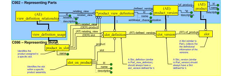
A Attachment_slot may have one or more versions (Attachment_slot_version), and each may have one or more applicable view definitions (Attachment_slot_definition). Each of these are subject to identification as described within capability C001: assigning_identifiers. In this respect, the model closely resembles that of Part described within capability C002: representing_parts.
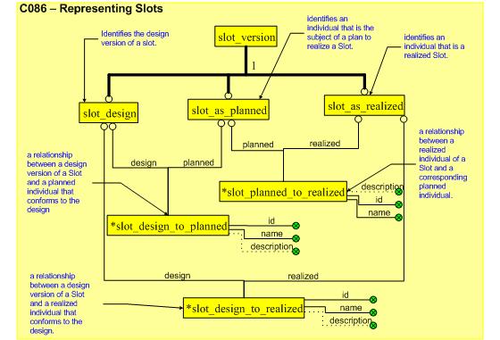
A Attachment_slot_version may exist in the form of a designed slot (Attachment_slot_design), a planned slot (Attachment_slot_as_planned) or a realized slot (Attachment_slot_as_realized).
As each is a version, the original Attachment_slot can be identified through the Attachment_slot_version's of_product attribute.
These versions correspond to the same PLCS approach to lifecycle management that are afforded to Parts, Product_as_planned and Product_as_realized described earlier in the busines section. The distinction between design, planned and realized products is also provided in capability C045: representing_product_as_individual (shortly to become representing_product_as_individual).
The relationships Attachment_slot_on_product and Product_in_attachment_slot identify the slot attached to a product and which part has been fitted to the slot, respectively.
The Attachment_slot_on_product relates a attachment_slot on one hand to a product on the other. The former links to the Attachment_slot_definition described below, while the other should link to a type of Product_view_definition (or a subtype such as Part_view_definition).
A Attachment_slot_definition is attached to a product through the relationship entity Attachment_slot_on_product. The Attachment_slot_definition has a defined_version attribute linking the Attachment_slot_version. This, in turn, has an attribute of_product which links to the Attachment_slot.
Since an assembly is built from relationships between Product_view_definitions and a Attachment_slot_definition is a subtype of this, there is a mechanism to include Attachment_slots within an assembly.
For the case of
In some cases there may be a requirement to mix these lifecycle definitions as some parts may be treated as products in their own right. For example, a pre-fabricated slot may already exist which can be planned for during the design stage.
The relationship Product_in_attachment_slot relates a Attachment_slot_definition to the Product_view_definition of the product occupying the Attachment_slot. The product attached may or may not be at the same stage of lifecycle as the the rest of the assembly (see notes above on consistency).
The relationships between;
- identifies the path through the lifecycle taken by a version (Attachment_slot_version of_product) of a slot ( Attachment_slot).
NOTE There are rules in the model to ensure that the same instance of Attachment_slot is used when relating Attachment_slot_design, Attachment_slot_as_planned and Attachment_slot_as_realized together using Attachment_slot_design_to_planned, Attachment_slot_design_to_realized or Attachment_slot_planned_to_realized.
A Attachment_slot may be identified whenever there two parts that are physically interfaced. If the details of this interface are required then the Attachment_slot may be associated with applicable instances of the Interface_connector and Interface_specification entity data types.
This capability covers both the representation of slots and the relationships between versions of slots. The process for generating these are described in the following sections.
The three steps to the PLCS approach are shown in the figure below.
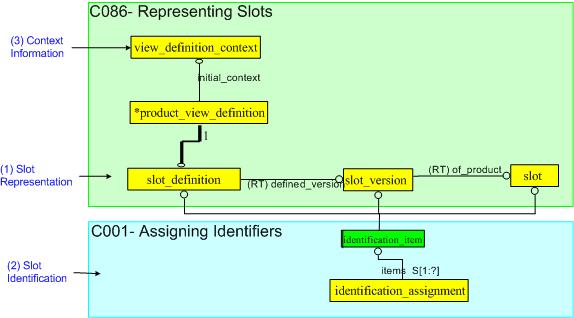
Step 1; The representation of a Slot is achieved through a number of related subtype entities, namely, Attachment_slot, Attachment_slot_version and Attachment_slot_definition. These entities are the subject of the identification described in step 2.
Step 2; The identification of the Slot is represented through the use of the Identification_assignment entity which is applied to each of the entities involved in representing the Slot. This only shows part of the identification method since this is described in the dependent capability, C001: assigning_identifiers.
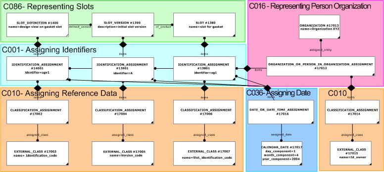
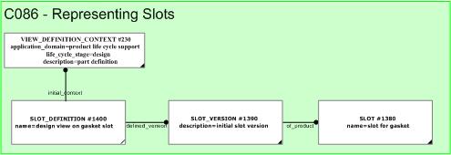
Step 3; The context of a Slot is represented through the use of the entity View_definition_context. These are necessary for the unambiguous referencing a Slot which further complements the identification in step 2.
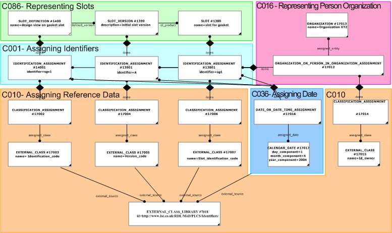
The classification representation which uses instances of external _class has a source, which is for PLCS purposes going to be provided in a reference data library (RDL). This is shown below.
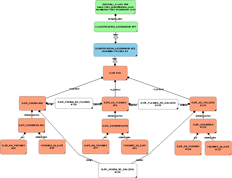
A Attachment_slot_version may exist in the form of a designed slot (Attachment_slot_design), a planned slot (Attachment_slot_as_planned) or a realized slot (Attachment_slot_as_realized).
These versions correspond to the same PLCS approach to lifecycle management that are afforded to Parts, Product_as_planned and Product_as_realized described earlier in the busines section. The distinction between design, planned and realized products is also provided in capability C045: representing_product_as_individual (shortly to become representing_product_as_individual).
Versions are identified through a version code (usually a number) while the original Attachment_slot can be identified through the Attachment_slot_version's of_product attribute.
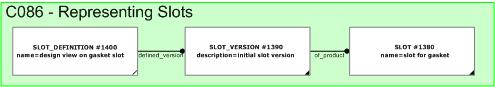
The following figures show the representation of these three types of versions.
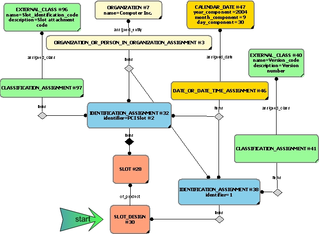
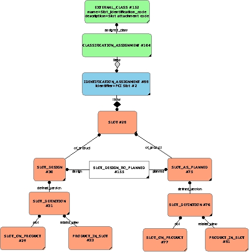
NOTE Both slot and slot design are shown having the same date/time for the assignments. It is likely the the slot is defined at the time of representing the design.
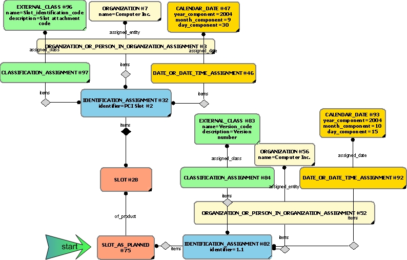
NOTE Both slot and slot as planned are shown having different date/time for the assignments. It is likely that the date of design is earlier than that of the process plan.
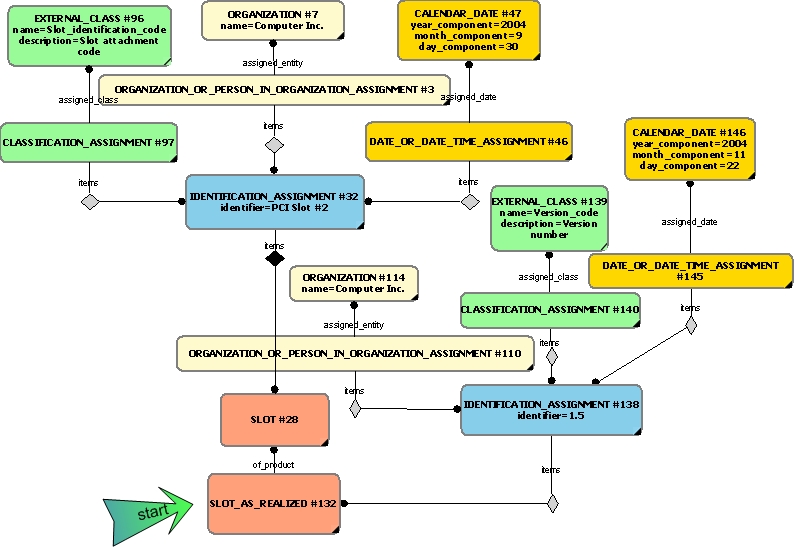
NOTE Both slot and slot as realized are shown having different date/time for the assignments. It is likely that the date of design and planned versions is earlier than that of the realized/as-built.
The relationships Attachment_slot_on_product and Product_in_attachment_slot identify the slot attached to a product and which part has been fitted to the slot, respectively.
The Attachment_slot_on_product relates a attachment_slot on one hand to a product on the other. The former links to the Attachment_slot_definition described below, while the other should link to a type of Product_view_definition (or a subtype such as Part_view_definition).
A Attachment_slot_definition is attached to a product through the relationship entity Attachment_slot_on_product. The Attachment_slot_definition has a defined_version attribute linking the Attachment_slot_version. This, in turn, has an attribute of_product which links to the Attachment_slot.
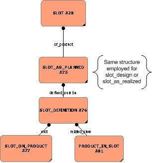
NOTE The same structure of elements are employed to represent both slot_design and slot_as_realized. These are not shown here. See capabiliity representing_slots for more details.
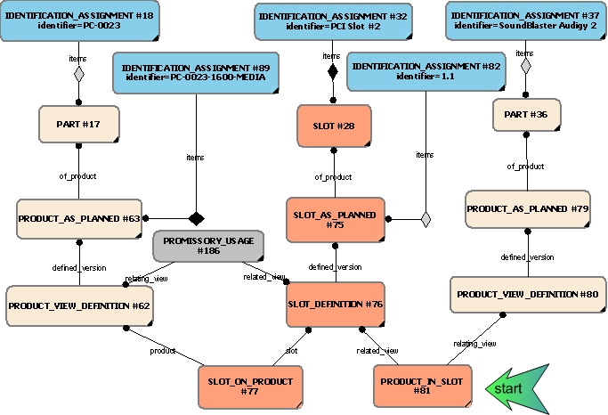
Since an assembly is built from relationships between Product_view_definitions and a Attachment_slot_definition is a subtype of this, there is a mechanism to include Attachment_slots within an assembly.
NOTE A complete assembly is not shown here - only the use of one contruct (promissory_usage) typically used in the representation of an assembly. Next_assembly_usage is another popular building block.
NOTE The slot in this case forms part of a simple assembly (through promissory_usage) and at the same time identifies the parent in the assembly as the product upon which the slot sits. A slot may be defined at any level in the assembly - not just the top level as shown here.
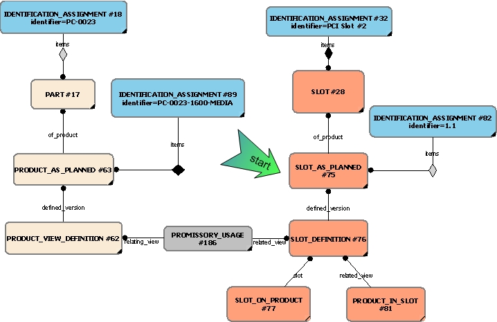
Representing a part or product that occupies a slot makes use of the Product_in_attachment_slot relationship which links a Attachment_slot_definition with a Product. The following figure shows the representation of a Soundblaster PC card occupying the slot defined which is part of the PC assembly. It also shows the use of the Attachment_slot_on_product which identifies the top-level product on which the Attachment_slot sits.
If the Attachment_slot_as_planned has been produced from a specific Attachment_slot_design, then the Attachment_slot_design maybe related to the Attachment_slot_as_planned by the relation entity Attachment_slot_design_to_planned.
If the Attachment_slot_as_realized has been produced from a specific Attachment_slot_as_planned, then the they maybe related by the relation entity Attachment_slot_planned_to_realized.
If the Attachment_slot_as_realized has been made from a Attachment_slot_design then it may also be related to that version of the design by the relation entity Attachment_slot_design_to_realized.
In cases where it is necessary to identify specific versions, the identification assignment of each should be specified. The figure below shows this.
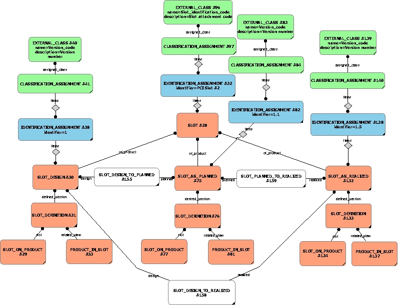
Referencing slots for the design was provided in an earlier section. The mechanism to refer to Attachment_slot_as_planned and Attachment_slot_as_realized is the same and is not repeated here.
The representation of a Slot is achieved through a number of related subtype entities, namely, Attachment_slot, Attachment_slot_version and Attachment_slot_definition. These entities are the subject of the identification described below.
The identification of the Slot is represented through the use of the Identification_assignment entity which is applied to each of the entities involved in representing the Slot. The identification assignment is subsequently
classified through the Classification_assignment entity. For a Slot, the classification assigned should be a "slot_identification_code". For a Attachment_slot_version the classification assigned should be a "Version_code". For a Attachment_slot_definition, the classification assigned should be a "Identification_code". The class assigned through this mechanism is normally represented
as an external_class as defined within an external_class_library. This is described more fully in the capability C010: assigning_reference_data. The identification assignment also has a responsible organization or person assigned to indicate the relevant owner using
the entity Organization_or_person_in_organization_assignment. This is explained in greater depth in the capability referencing_person_organization![]() Error C1: Capability referencing_person_organization not in dex_index.xml
Error C1: Capability referencing_person_organization not in dex_index.xml
. Additionally, a date and / or date and time may optionally also be assigned to the identification assignment using the entity
Date_or_date_time_assignment. This is described in greater depth in the capability C036: assigning_date_time. This process of identification is described in the dependent capability, C001: assigning_identifiers.
The context of a Slot is represented through the use of the View_definition_context entity which is described in greater detail in capability C002: representing_parts.
The following sections define a set of templates for the capability, where a template is a specification of a set of entities that need to be instantiated to represent a given set of information.
This section specifies the template referencing_slot.
NOTE An explanation of a template and the associated instantiation path is provided in the Template overview section.
This template describes how to represent @@@@


target
is the parameter to which the
External_class
is bound.
| Entity in path | Value | Inherited from |
| Identification_assignment.identifier | @id | — |
| Identification_assignment.role | '/IGNORE' | — |
| Identification_assignment.description | '/NULL' | — |

The instance model in STEP XML exchange file format (ISO 10303 Part 28 ed.2 syntax) is:#1 = TASK_METHOD($,$,$,$,()); #2 = EXTERNAL_CLASS('/IGNORE','Safety_critical',$,#3); #3 = EXTERNAL_CLASS_LIBRARY('urn:plcs:rdl:std',$); #4 = CLASSIFICATION_ASSIGNMENT(#2,(#1),'/IGNORE');

NOTE this characterization is optional.
The date when the Work_order and the Directed_activity was issued can be represented by assigning a date (using the relationship Date_or_date_time_assignment) to the Work_order and the Directed_activity using the assigning_calendar_date template with the Date_time being classified as a type of "Date actual release" (urn:plcs:rdl:std:Date actual release).
NOTE The assignment of dates is described the capability C036: assigning_date_time.
This capability "representing slots" is related to the following capabilities:
This capability "representing slots" is dependent on the following capabilities:
The following classes of reference data are required for this capability:
[Slot_identification_code]© OASIS 2010 — All rights reserved