| Capability (C003):— representing_assembly_structure | Date: 2010/08/26 07:31:30 Revision: 1.30 |
This section provides a business level overview of this capability.
This capability supports explicit hierarchical product structures (e.g. using Next_assembly_usage) representing assemblies and the constituents of those assemblies. The consituents maybe at the detail level of Parts (to describe the design assembly) or Product_as_individuals (to describe the assembly of a manufactured, individual product), or other sub-assemblies of each.
Assembly structures are used for parts and sub-assemblies used in the design and manufacturing life cycle phases. But assemblies may also be used for a manufactured product and its (selective) constituents, in the support stages. Keeping track of individuals and their individual components, such as an aircraft and its engines, is an example of this. An individual product is normally identified by a serial number, as opposed to the type identification, a part number or type code, but apart from that there is not much difference between assemblies of parts and individual products.
This capability uses the Part assembly as a starting point for the description of assemblies, but most of the examples are directly applicable to Product_as_individuals.
An explicit part structure corresponds to the traditional engineering and manufacturing bill of material (BOM) indentured parts list. Relationships between (Part_view_definitions are the principle elements used to structure an explicit part assembly configuration. The relationship itself represents a specific usage of the constituent part definition within the immediate parent assembly definition. Mechanisms to represent quantities associated with this Assembly_component_relationship usage are also provided.
It also has the capability to identify and track a specified usage of a component definition in an assembly at a higher level than the immediate parent subassembly. Consider a wheel-axle subassembly composed of one axle and two wheels, the right and the left. A higher-level chassis assembly is in turn composed of two wheel-axle subassemblies, the front and the rear. The requirement to individually identify the left-front wheel, for example, is supported by this capability.
Different view definitions of the same version of a part may participate in different explicit product structures. For example, a design/as-planned view of a particular version of a part, representing the design discipline part definition, may be engaged in an explicit design assembly structure. A manufacturing/as-built view of the same part version represents the definitional template for the actual physical part, and may participate in a manufactured assembly structure that is different from the design assembly structure. Finally, a support/as-maintained view of the part version representing the physical part definition may participate in yet another different disassembly structure.
In addition to hierarchical assembly structures, it supports other relationships between part definitions that exist to characterize the make from relationship and for supplied part identification.
An assembly structure that consists of Parts, may also contain Attachment_slots. This is discussed within the Additional Usage Guidance.
It is however not allowed to mix Parts and Product_as_individuals in the same assembly structure. Such structures may be created, but using a Breakdown, consisting of Breakdown_elements, which each could be realized either as a Part or as a Product_as_individual. See C004: representing_breakdown_structure for more information.
This section provides an overview of the information model that supports this capability.
This capability provides mechanisms for the representation of assembly structures as;
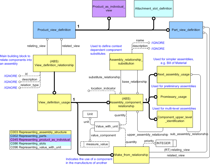
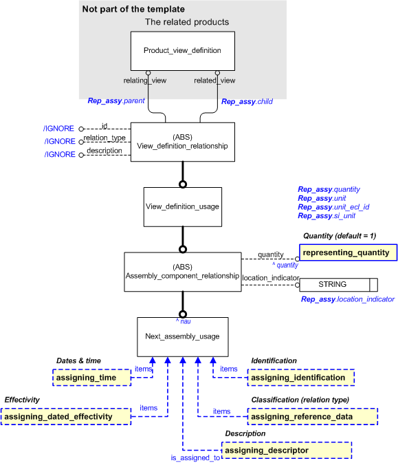
Assemblies, as the term suggests, involve relationships between the various component parts of the assembly. Different relationships are used to convey the different types of assemblies and their associated data. These relationships are shown below in the Express-G diagram;
NOTE The diagram does not show all details for entities described in other capabilities.
The Next_assembly_usage entity is used for most assembly structures. It is a subtype of several other entities:
NOTE In another context, the structure of the assembly may be described differently, adding, for example, an intermediate level between the products.
NOTE The relating product is the parent, the related product is the child.
It furthermore
identifies a possibly quantified usage of a product version as a component of another product version.
In case the component is a part, the following apply:
In case the component is a non-countable material, the following apply:
EXAMPLE An assembly may require inclusion of ten grams of grease.
The Assembly_component_relationship also provides a means to identify a location of the component part being related to the parent asembly (known as a "find number").
Promissory_usage establishes a relationship between a (related) component and some higher-level assembly (relating) that is not the immediate parent in the hierarchy. An example of this would be a preliminary BOM, where the exact assembly structure is not yet known or identified. This is further described in Promissory Component Usage.
Component_upper_level_identification may be used to indicate the assembly top node, as well as a strict parent-child relationship. This is useful in order to distinguish a specific occurrence of a component in an assembly of more than two hierarchical levels, and is further described in Multi-Level Assembly Digital Mock-Up.
The Make_from_relationship identifies the fact that a part is manufactured from another part. See Make_from_relationship.
The Assembly_relationship_substitution is used to identify substitution assemblies. STEP designates alternate and substitute parts differently. Alternate parts are interchangeable in all occurrences whereas substitutes are interchangeable only in a particular usage. The substitute relationship is context dependent - as the substitute is only valid in the context of its usage as a component within the specified parent assembly definition. This is further described in Substitute Components in an Assembly. Alternate parts are described in C002: representing_parts.
A Product_view_definition is a characterization of a Product_version, relevant in one or more application domains and for one or more life cycle stages. It is a collector of the properties that characterize the defined version of a product. In AP239, Product is an abstract entity, so only its subtypes may be instantiated. The entities for the valid subtypes used in an assembly structure are described in greater detail in capabilities C002: representing_parts, C045: representing_product_as_individual, and C086: representing_slots.
NOTE As mentioned before, this guidance offered here is primarily targetted towards the structures required to represent the assembly of the design (i.e. using parts). However, the same principle mechanisms provided here may be used for other lifecycle stages and for other subtypes of Product. This is further discussed in each subsequent section.
This capability supports explicit hierarchical assembly structures representing assemblies and the constituents of those assemblies. A constituent of an assembly may itself also be an assembly (a sub-assembly), which in turn is made up of constituents. Detail components make up the leaves of these hierarchical structures, and may be parts (C002: representing_parts), individual products (C045: representing_product_as_individual), slots (C086: representing_slots) or interfaces.
NOTE Structures can be built for all subtypes of Product, but other subtypes use different mechanisms, e.g. Breakdown_elements are structured using Breakdown_element_usage rather than Next_assembly_usage, Requirements use Tracing_relationship, and Documents use Document_definition_relationship.
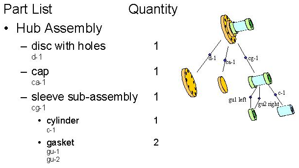
An assembly structure consisting of sub-assemblies and Parts corresponds to the traditional engineering and manufacturing bill of material parts list, and is used as an example here.
Each individual node in this hierarchy is used to identify and place the components in the assembly. The nodes in the product structure each have a corresponding entry in the part list, with indenture level corresponding to depth in the structure. The components are represented through instances of Product_view_definition. The hierarchy is built through a set of relationships.
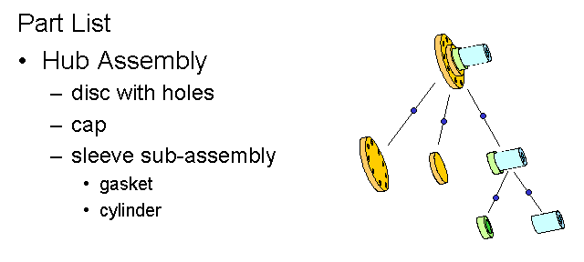
NOTE The example presented above and further on has been taken (and adapted) from the PDM Schema User Guide. It is hoped that this will help those familiar with the PDM Schema to be able to see how the two models overlap.
Each relationship is represented by an instance of Next_assembly_usage which relates two instances of Product_view_definition or one of its subtypes, e.g. Part_view_definition. Each Product_view_definition has a defined_version and each Product_version has an attribute (of_product) which identifies the type of Product which has been defined as a component in the assembly. The capability C002: representing_parts describes the steps required to represent Parts.
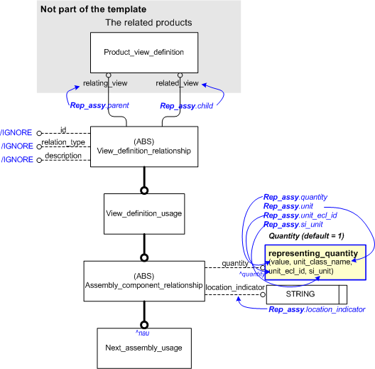
The attribute relating_view of Next_assembly_usage always relates to the higher level assembly (the parent), and the related_view attribute relates to the component (the child). The relationship itself represents the usage of a constituent definition within the immediate parent assembly definition. In the simplest form, this structure corresponds to a basic indentured parts list as shown in Figure 2. An Express-G overview diagram showing the entities used is found in Figure 1.
NOTE No cyclic Product_view_definition structures may be defined.
The attribute id should always be set to "/IGNORE". An identifier may be assigned to a Next_assembly_usage using C001: assigning_identifiers classified as a "Relationship identification code" (urn:plcs:rdl:std:Relationship identification code), but for simple assembly structure that is not necessary.
The attribute relation_type should always be set to "/IGNORE". An optional classification of Next_assembly_usage can be assigned using a subclass of the external reference data class "Next assembly usage" (urn:plcs:rdl:std:Next assembly usage). Simple assembly structures do not require any specific classification.
The attribute description should always be set to "/IGNORE". An optional description could be assigned to the Next_assembly_usage using C095: assigning_descriptor. Simple assembly structures do not need a descriptor.
The attribute location_indicator should only be used if the exact occurrence of a component within the assembly is required (see Multiple Individual Usage Occurrence). For simple assembly structures it should be un-set.
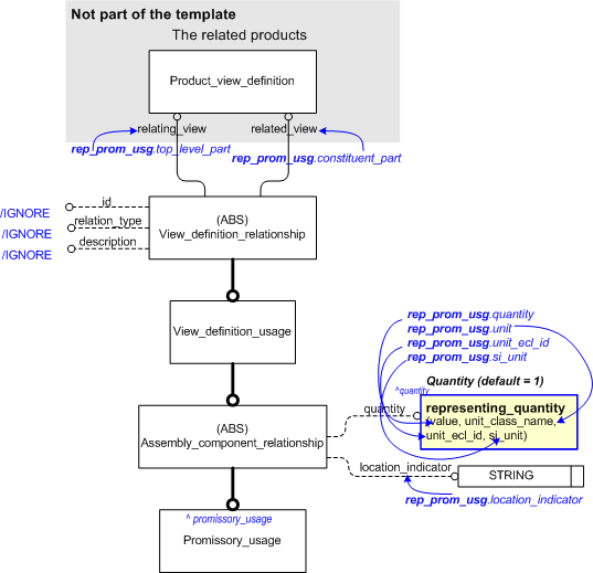
The attribute quantity is a relation to a Value_with_unit, and is described in the following section.
An example instantiation of the EXPRESS entities and attributes used to support the requirements of basic explicit assembly structure are shown in Figure 3. For simplicity in this example, there are three items represented from the hub example diagram above; i.e. the Hub Assembly, the Sleeve Assembly and the Gasket.
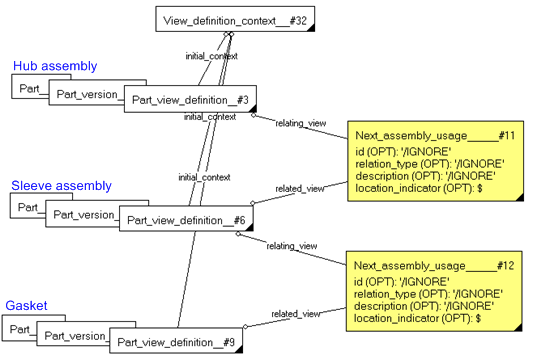
NOTE This diagram shows instances denoted by a box with lower-right triangle (may be filled or not). The entity instance name appears first in the box, followed by the instance number (e.g. #400). The lines between the boxes represent attributes which form relationships from one to the other (in the direction of the line ending in a small filled circle ---o). The name of the attribute is placed on or near the line drawn between by boxes. Set-relationships (many-to-many) are indicated by e.g. "S[0:?]" after the name (this example says that it is a set from zero to many). The simple attributes (i.e. those that are not relationships) and their values are shown inside the box.
NOTE The identification and details of Part, Part_version, Part_view_definition and View_definition_context are described in C002: representing_parts.
NOTE The sub-component being represented is always contained in relating_view whereas the item to which it is being related is contained in the related_view.
The basic explicit assembly described above (BOM) represents a single occurrence of the component definition within the assembly definition. This is adequate until there is a need to identify either, more than one occurence, or specific individual occurences of a part. For example, it is normal that the same Part is used in many places within an assembly. Thus, the design representation of a nut (in a bolt-and-nut assembly) may not change, but there may be a need to determine the quantity used within the whole assembly. On the other hand, it may also be necessary to differentiate between those that are used in one part of the assembly from another. An example of this might be the need to specify different torque requirements depending upon where in the assembly the nut is used. Hence, multiple occurences of a design Part may be required. Multiple occurrences of a constituent used in an assembly are represented in two ways in the PLCS Schema:
The Abstract entity Assembly_component_relationship (supertype of e.g. Next_assembly_usage) associates a quantity with the component usage (hence quantified usage), but does not allow independent identification of individual occurrences when a component definition is used multiple times. This quantified usage simply relates a quantity value with the multiple component occurrences; it does not distinguish the individual occurrences independently. The quantified usage occurrence is most commonly used for standard component parts, such as fasteners, that need to be quantified but do not need to be individually distinguished. This structure corresponds to a basic indentured parts list with the associated part quantity values (see Figure 4 below).
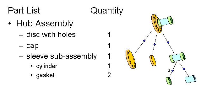
As with the basic indentured parts list, each node in the part structure assembly is uniquely identified, representing the definitional template for the component or assembly. The nodes of the product structure each have a corresponding entry in the part list, with the indenture level corresponding to depth in the assembly structure. The quantity of each usage occurrence is identified in the parts list - the single occurrence usage has an implicit quantity of one. In this example, the relationship between the gasket component definition and the parent sleeve subassembly is represented by a quantified component usage to denote two occurrences of the gasket definition used in the parent sleeve subassembly.
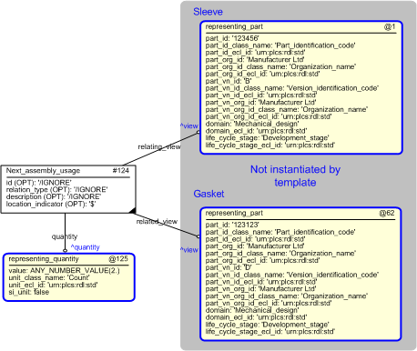
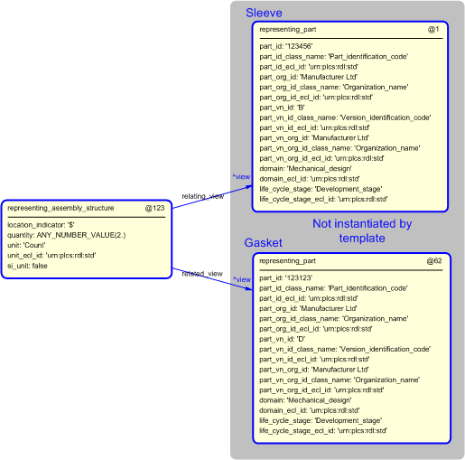
The instantiation of the EXPRESS entities and attributes used to support the requirements of basic explicit assembly structure are shown in Figure 5. For simplicity in this example, there are three items represented from the hub example diagram above; i.e. the Hub Assembly, the Sleeve Assembly and the gasket.
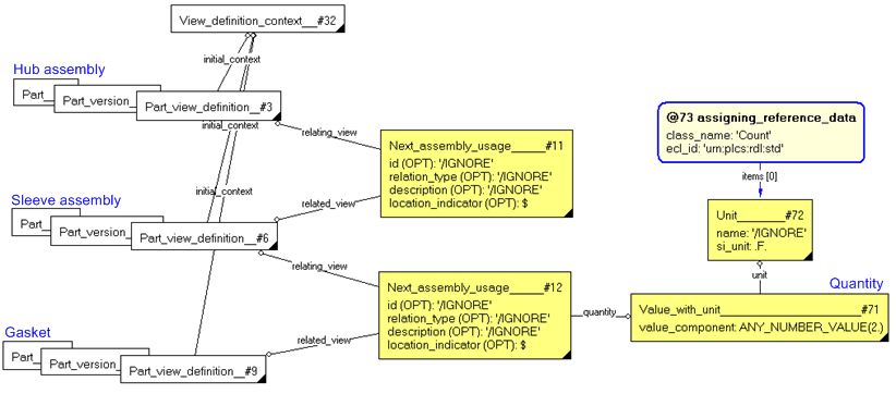
NOTE It is not necessary to assign a classification using external reference data or to instantiate the optional location_indicator attribute for an instance of Next_assembly_usage in the context of a quantified parts list.
There are three main points to note.
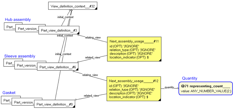
The same example is shown below in Figure 6, but with the use of a template called representing_count instead of a direct instantiation of each entity. The end result, what is actually instantiated, is exactly the same in both cases, since the template takes care of the instantiation of the entities Value_with_unit and Unit for us. Templates are used for controlled and consistent instantiation, and is also a way to simplify the diagrams, but still show all important parts, and they will be used in the following examples
Multiple Individual Usage Occurrence
The quantified usage mechanism provided above identifies the component quantity, but does not allow independent identification of the individual occurrences when a component definition is used multiple times.
The PLCS Schema uses separate single usage occurrences to represent multiple occurrences of a component within an assembly when the various components must be distinguished individually. Multiple occurrences of a component within an assembly must be individually identified to allow separate identification, display names, reference designation, or related property information, including shape and orientation/transformation information.
For example, consider a component that is a flexible pipe. The geometrical representation assigned to the definition of that component may be a simple I shaped tube. The geometrical representation associated with one occurrence of the pipe positioned in a parent assembly may be an S shape, as constrained by the assembly environment. A second occurrence of the pipe definition may be used in the same parent assembly, but in a different position. The geometrical representation assigned to this occurrence may be an L shape due to different constraints from the different position of the component within the parent assembly.
This structure corresponds to a basic indentured parts list with the associated part quantity values where the individual component occurrences are individually identified (see Figure 7 below).
As with the basic indentured parts list, each node in the part structure assembly is managed separately, providing the definitional template for the component or assembly. The nodes of the product structure each have a corresponding entry in the part list, with the indenture level corresponding to depth in the assembly structure. The quantity of each usage occurrence is identified in the parts list - the single occurrence usage has an implicit quantity of one. In this example, the quantity is represented by two occurrences of the relationship (Next_assembly_usage) entities between the gasket component definition and the parent sleeve subassembly.
The instantiation of the EXPRESS entities and attributes used to support the requirements of basic explicit assembly structure are shown in Figure 8 below. For simplicity in this example, there are three items represented from the hub example diagram above; i.e. the Hub Assembly, the Sleeve Assembly and the gasket.
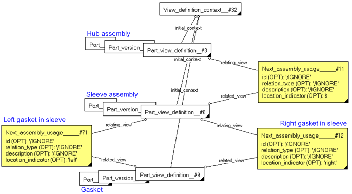
NOTE The Next_assembly_usage entity should be instantiated once for each individual occurrence of a component definition (Part_view_definition) used in the parent assembly. The sum of single instances of Next_assembly_usage that exist between an assembly definition and a component definition represents the total quantity of component occurrences used in the parent assembly.
NOTE The default quantity is 1, so the need to specify a "single usage occurrence" is entirely optional.
Parts Lists and Item Find Number
The following example illustrates the mechanical drawing and corresponding parts list for two typical example assembly parts, PCB A and PCB B. Each drawing illustrates the use of the item find number.
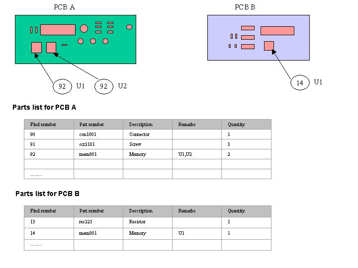
In the example above, the same component (part number mem801) is used in both assemblies PCB A and PCB B. However, the item find number is different for each assembly. The item find number assigns to the component a name that is specific to the assembly in which it is being used. In the PLCS Schema this is done through the location_indicator attribute of Next_assembly_usage (an inherited attribute of Assembly_component_relationship).
NOTE In the PDM Schema, the item find number may be assigned to the name attribute of Next_assembly_usage_occurrence.
NOTE This "find number" is an identifier of the component in a specific assembly, not of a component on a drawing ("item references"), which is an identification of a component in a specifc drawing irrespective of assembly. The mapping of drawing find number or item reference should be in the relationship between the drawing or drawing parts list and the component.
The Next_assembly_usage.location_indicator attribute should be populated where an item find number has been associated with the component in the assembly. If there are more than one usage occurences of the component on the drawing, then multiple component usages (see above) should be instantiated. Each instance should then receive it's own location_indicator value according to the item find numbers assigned. The location_indicator need not be unique across different assemblies. However, item find numbers of components within the same assembly level should be consistent and unique. A descriptor may be assigned to a Next_assembly_usage as described in C095: assigning_descriptor, containing a unique display name (usage 1, usage 2 etc.) for presentation of the assembly structure.
The same attribute should be used if the Part occurrence is instantiated as a Promissory_usage or Component_upper_level_identification (see below).
NOTE The sum of single instances of Next_assembly_usage that exist between an assembly definition and a component definition represents the total quantity of component occurrences used in the parent assembly. Each instance of component (instance of part_view_definition) may have one or more item find number associated with it through different next_assembly_usage.location_identifier attributes.
The STEP PLCS Schema supports promissory usage relationships between components and some higher-level assembly that is not the immediate parent in the hierarchy. This may be important to relate an outsourced component to a top-level assembly definition related to a configuration and product concept. A supplier may only require the configuration and end item identification that is associated with the component of interest, and may not need to know the detailed assembly structure in between.
An instance of Promissory_usage specifies the intention to use the constituent in an assembly. It establishes a relationship between an assembly and a component, regardless of the number of intermediate levels between them (which may be established with instances of Next_assembly_usage). See Figure 1 for an Express-G overview. It may be used when the product structure is not completely defined, e.g. during early design phases to create preliminary BOMs for prototyping.
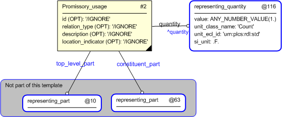
The attribute location_indicator should be set to "/IGNORE" for Promissory_usage. It is not meaningful to talk about the location for a promissory usage.
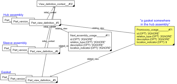
Note that design view on the gasket is related directly to the hub assembly via the Promissory_usage entity, rather than through the sleeve sub-assembly.
PLCS also provides the capability to identify individual occurrences of a component in a multi-level assembly. This gives us the ability to assign to each occurrence an identifier, a position in the assembly, a geometrical representation, or other properties that may be different from that assigned to the part definition of the component.
In order to distinguish a specific occurrence of a component in an assembly of more than two hierarchical levels, the Component_upper_level_identification entity is used. For example, a wheel-axle subassembly is composed of an axle and two wheels, the right and the left. A higher-level chassis assembly is in turn composed of two wheel-axle subassemblies, the front and the back. The requirement to individually identify the right-front wheel, for example, is supported by this capability.
This would be instantiated using an instance of Component_upper_level_identification to represent the left-front wheel. The related_view attribute references the Part_view_definition of the component wheel. The relating_view_definition attribute references the Part_view_definition of the higher-level chassis assembly. The attribute sub_assembly_relationship is a reference to the Next_assembly_usage that represents the left wheel occurrence in the wheel-axle subassembly. The attribute upper_assembly_relationship is a reference to the Next_assembly_usage representing the front occurrence of the wheel-axle subassembly within the higher-level chassis assembly.
Figure 12 shows, continuing on with our previous example, an indentured parts list with associated part quantity values and individual identification of the specific component occurrences used within a multi-level assembly.
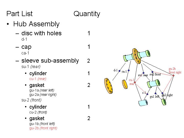
In the figure above, the Component_upper_level_identification cu-1 of the cylinder (c-1 in a sleeve subassembly) within the rear sleeve (su-1 in a hub assembly) of the higher-level hub assembly is illustrated. Also illustrated is the right gasket (gu2 within a sleeve subassembly) within the front sleeve (su-2 within a hub assembly) of the higher-level hub assembly, individually identified as gu-2b. Each Component_upper_level_identification of the gasket, as well as that of the cylinder, could be individually identified using C001: assigning_identifiers, although the identification of both Next_assembly_usage and Component_upper_level_identification are optional, since they are indirectly identified by the components and assemblies they are related to.
The instantiation of the right gasket of the right sleeve assmbly in this example is shown in Figure 12. An Express-G overview of the entities involved is found in Figure 1.
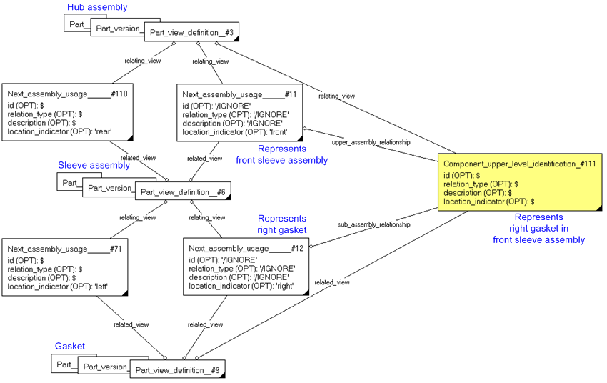
There are a number of points to note. Firstly, there are two occurences of an assembly-component relationship (sleeve-to-gasket), differentiated by the respective locations (left and right) of the gasket in the assembly. Secondly there are two occurences of the assembly-sub-assembly relationship (hub-to-sleeve) within the assembly, again differentiated by the respective position (front and rear) of the sleeve. Thirdly there is one instance of Component_upper_level_identification that identify exactly the right gasket in the front sleeve assembly.
Different view definitions of the same version of a Part may participate in different explicit product structures in the PLCS Schema. For example, a design/as-planned view of a particular version of a part, representing the design discipline Part definition, may be engaged in an explicit design assembly structure. A manufacturing/as-built view of the same part version represents the definitional template for the actual physical part, and may participate in a manufactured assembly structure different from the design structure. Finally, a support/as-maintained view of the part version representing the physical part definition that may participate in yet another different disassembly structure. The figure below illustrates two different views on a part structure.
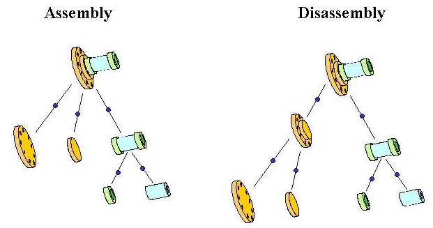
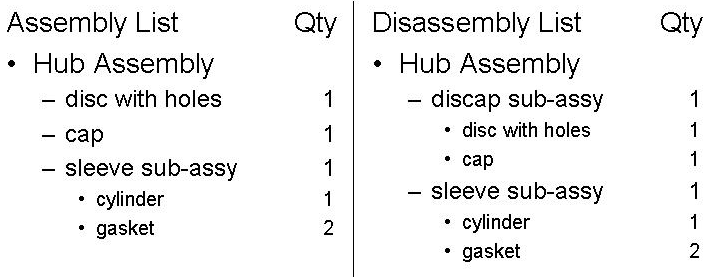
Many of the parts that make up the 'nodes' in the two different assembly structures in the above figure have the same base identification - they simply have multiple definitions from different life-cycle viewpoints. The disc with holes, the cap, and the sleeve sub-assembly are all present in both views of the part structure. However, in this example there is also a new 'node' in the disassembly structure. It corresponds to a sub-assembly, composed of a disc with holes and a cap, which was not present in the assembly structure (see the figure below).
The Express entities and relationships that support the requirements of alternate life-cycle viewpoints on product structure are the same as those already described for part structures. Recall that the structural element of the part master 'node' is the Part_view_definition entity, representing a view definition of a part version. The previous description presumed that each part master element in the assembly structure had a consistent life-cycle view definition - a single assembly structure from a single view definition context.
In this example of multiple part structures, the part master information corresponding to the 'nodes' disc with holes and cap (and sleeve sub-assembly plus its components) each has two part view definitions. One view definition may represent, for example, the design or manufactured assembly structure; the other a maintenance or disposal disassembly structure. Both of the view definitions are related to the same part version. In this way, the information that is common across the different part structures (the base version identification for all 'nodes' that have definition in both structures) is represented only once. Information that is different between the different views, such as associated management data, property information, or in this case product structure itself is managed independently by using different product_definitions.
The assembly structure would be constructed between the part view definitions within the same appropriate view context, say for example design.
The disassembly structure would also be constructed between Part_view_definition instances representing a different life-cycle stage, for example maintenance. Present only in the disassembly structure, the new or "phantom" part is a sub-assembly composed of a disc with holes and a cap - it is not present in the assembly structure. The part master information corresponding to this "hubcap" sub-assembly need only have a single part view definition in the appropriate life-cycle stage, e.g. maintenance. The complete disassembly structure is constructed using this part_view_definition, along with those of the other component part masters for that same view context.
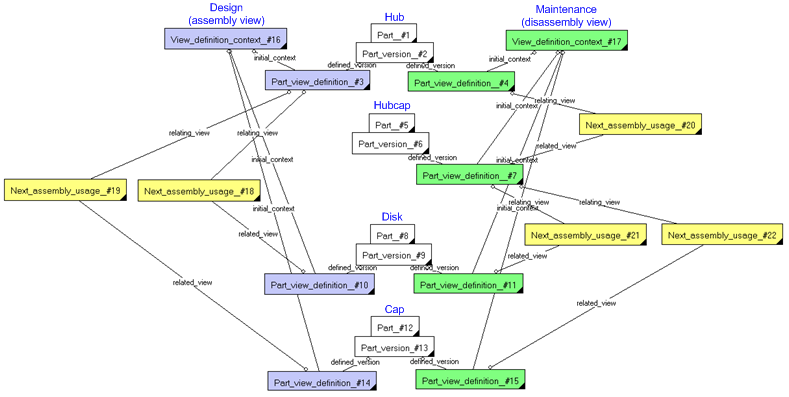
NOTE Colours are used in this diagram to differentiate entity instances. Blue instances are the design view_definition_context and the Part_view_definitions belonging to that context, and the green instances are similarly for maintenance. The yellow Next_assembly_usage instances creates the two different structures, the assembly structure (design) to the left, and the disassembly structure (maintenance) to the right.
NOTE The above diagram have been simplified for the sake of clarity. All attributes have been hidden. The attributes for Next_assembly_usage are all set to "/IGNORE", except the location_indicator attribute, which is un-set. Attributes and all other details regarding the definition of a Part are described in C002: representing_parts.
Substitute Components in an Assembly
Substitute components in an assembly are identified as a specific relationship (Assembly_relationship_substitution) between two instances of Next_assembly_usage (or between two other subtypes of Assembly_component_relationship). The two instances must share the same parent assembly definition (e.g. Part_view_definition) through their respective relating_view attributes. The two substitute components are identified through the related_view attributes of each Next_assembly_usage. Substitute components are context dependent as the substitute is only valid in the context of its usage as a component within the specified parent assembly definition.
NOTE An alternate part relationship (described in capability C002: representing_parts) is context free, i.e. an alternate part may be used instead of the base part in any assemblies or contexts.
The Express entities and attributes used to support the requirements of substitute part identification are illustrated in Figure 1. An instance diagram example is shown below.
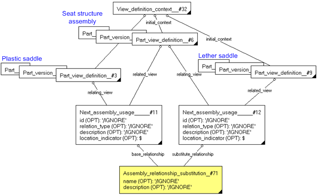
The diagram above shows two Next_assembly_usage instances (#11 and #12) associated (via their respective relating_view attributes) with the Part_view_definition of the Saddle structure assembly (#6). Each of these assembly definitions (#11 and #12) relate a different component (part_view_definition's #3 and #9) through their respective related_view attributes. The assembly_relationship_substitute simply relates the two alternatives as a base_relationship (#11) or as a substitute_relationship (#12).
NOTE There is no restriction saying that the View_definition_context must be the same for the involved Part_view_definitions, as in the above diagram, although that may be the natural option.
All attributes of Assembly_component_relationship, should be set to "/IGNORE".
An Assembly_relationship_substitution defines a one-way substitution: if A is specified as a substitute for B, B is not implied to be a substitute for A. In the above example, the leather saddle may be used as a substitute for the plastic saddle in this particular saddle structure assembly. There is no indication that such a substitution may occur in any other assemblies, nor does it imply that the leather saddle may be substituted by the plastic saddle.
NOTE The instance of the substitute constituent does not require the same spatial relationship or the same quantity. A substitute constituent does not require equivalent form, fit, and function of the constituent for which it is a substitute.
NOTE As instances of Assembly_component_relationship establish assembly relationships relevant in the definition contexts of the assembly, the substitution only apply in these contexts.
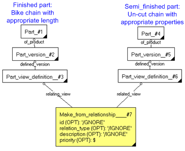
In PLCS, the fact that a part is manufactured from another part is indicated by a Make_from_relationship entity instance. It relates the source part definition in the related_product_definition attribute to the resultant part definition in the relating_product_definition attribute.
A make from relationship should be used when a part is made out of a semi-finished product (part), or when it is made out of raw material that has a detailed specification and is managed as a part. An example of the first would be manufacturing-to-stock (semi-finished product) and manufacturing-to-order (where the items in stock are cut, modified, or finished in some other way to form the final product. Another eaxmple could be the making of the ring with holes from the above examples, if the ring was made from a sheet of steel with certain properties.
NOTE The make_from_realtionship is used when one part is made from another part. If there is no need to treat the raw material as a part, a product property for the material could be used (see C076: assigning_product_properties).
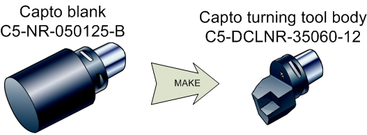
The example above shows a "Capto blank" to the left, a semi-finished product, which is modifed for a specific fitting of a cutting tool assembly "Capto turning tool body" to the right. The "Capto turning tool body" is then assembled with other parts to form different specific turning tools. The relationship between the "Capto turning tool body" and the "Capto blank" would be represented using a Make_from_relationship.
The EXPRESS entities and attributes used to support the requirements for Make_from_relationships are illustrated in Figure 1.
A Make_from_relationship is a type of View_definition_usage established between two instances of Part_view_definition. It specifies that, in the context of the definition of the relating part version, the relating part version is considered as resulting from the manufacturing transformation of the related part version.
The attribute id should be set to "/IGNORE". An identifier may be assigned to a Make_from_relationship using C001: assigning_identifiers.
The attribute relation_type should be set to "/IGNORE". A classification may be assigned to a Make_from_relationship using C010: assigning_reference_data, e.g. to denote the process of transformation used. The external class should be a subclass of "Make from relationship" (urn:plcs:rdl:std:Make from relationship).
NOTE The characteization of the process of transformation from the related part version to the relating part version it out of the scope of this capability.
The attribute description should be set to "/IGNORE". A descriptor may be assigned to a Make_from_relationship using C095: assigning_descriptor.
The attribute priority should be used if a part could be made of more than one other parts, and there is a preference for which one to use. This value is an integer that only has meaning when comparing it with corresponding values for Make_from_relationship sharing the same relating_view. If present, the priority attribute is a relative ranking value, not an absolute ranking. A lower value (e.g. "1") indicates a higher preference for the related_view, and a higher value indicates a lower preference.
NOTE Details about the parts, such as identification and properties, are not shown in the diagram above. See C002: representing_parts for further information.
This section specifies how the information model can be further characterized by the assignment of additional information such as dates, approvals and people or organizations.
The following characterizations may apply.
Dates and Time can be assigned to a Next_assembly_usage, a Promissory_usage, a Component_upper_level_identification, and to a Assembly_relationship_substitution. The assignment of date or time is a good practice, and a necessity for historical records of changes to the structure, and is therefore strongly recommended.
NOTE Date and time cannot be assigned to a Make_from_relationship. Use effectivity (see below) instead.
Dates are also assigned to approvals and effectivities (see below), so when any of these are assigned to an item, there will be a date set. In those cases, there is no need to assign a specific date as well. A pure date or time assignment is more like a system generated time stamp for system events, e.g. creation, deletion.
NOTE A thumb rule is that if the event (which causes a date or time assignment) involves a human decision, approvals or effectivity should be used.
The date or date and time must be assigned in a given role, such as "Date actual creation" (urn:plcs:rdl:std:Date actual creation). The role of the date assignment is represented by classifying the assignment by the use of external reference data (see C010: assigning_reference_data). The reference data class must be a subclass of "Date or date time assignment" (urn:plcs:rdl:std:Date or date time assignment).
NOTE Time is classified using the same reference data as Dates, i.e. an assigned time (a date plus hours, minutes and seconds, and time zone) may be classified as "Date actual creation" (urn:plcs:rdl:std:Date actual creation).
The assignment of date and time is described in the capability C036: assigning_date_time. Since Time is more accurate than a calendar date, the assignment of time is recommended.
Effectivity may be assigned to instances of Next_assembly_usage, Promissory_usage, Component_upper_level_identification, and to instances of Assembly_relationship_substitution and Make_from_relationship.
The assignment of effectivity is described in Capability C006: assigning_effectivity.
An approval may be assigned to instances of Next_assembly_usage, Promissory_usage, Component_upper_level_identification, and Assembly_relationship_substitution.
NOTE Approvals cannot be assigned to a Make_from_relationship. Use effectivity (see above) instead.
Approvals are always accompanied by an approval status, as defined in external reference data, and by a date or time for the approval, as well as the approving person or organization. Approvals are assigned as described in capability C019: assigning_approvals.
All subtypes of View_definition_relationship may be given one or more identifiers, although none is required.
NOTE Identifiers cannot be assigned to a Assembly_relationship_substitution.
Identifiers are assigned in a given role, such as "Owner of" (urn:plcs:rdl:std:Owner of), or "Creator of" (urn:plcs:rdl:std:Creator of), and the identifier is considered unique within the context of the given Organization (see further Capability C001: assigning_identifiers).
All subtypes of View_definition_relationship, and Assembly_relationship_substitution, may be classified, but none is required.
Classification is assigned using external reference data, and is described in Capability C010: assigning_reference_data. The class assigned must be a subtype of the external reference data class representing the entity itself, e.g. the class assigned to a Next_assembly_usage instance should be a subclass of "Next assembly usage" (urn:plcs:rdl:std:Next assembly usage).
NOTE No subclasses have been defined in this capability. Examples of such classes would be 'manufacturing assembly', and 'design assembly'., although they would have to be defined in business specific reference data libraries, to be used.
A Descriptor (a descriptive text string) can be assigned to all subtypes of View_definition_relationship, and to Assembly_relationship_substitution. It should always be classified as "Description" (urn:plcs:rdl:std:Description).
The assignment of descriptors is described in the capability C095: assigning_descriptor.
Documents can be assigned to instances of Assembly_relationship_substitution and Make_from_relationship. Documents are assigned in a given role, such as "Definition", "Specification", or "Description". The role of the assignment is represented by classifying the assignment using a subclass of external reference data class "Document" (urn:plcs:rdl:std:Document). Specific reference data classes may be defined in business specific external reference data
The assignment of documents is described in the capability C005: representing_documents.
An organization can be assigned to a Next_assembly_usage, Promissory_usage, Component_upper_level_identification, and Assembly_relationship_substitution.
NOTE Organizations cannot be assigned directly to a Make_from_relationship, only together with an identifier (see above).
The organization must be assigned in a given role, such as "Owner of" (urn:plcs:rdl:std:Owner of) or "Creator of" (urn:plcs:rdl:std:Creator of). The class must be a subclass of "Organization or person in organization assignment" (urn:plcs:rdl:std:Organization or person in organization assignment). Further classes may be defined in business specific external reference data.
The assignment of an organization is described in C094: assigning_organization
Since all examples above relate to design, here are some guidelines for product structures where the constituents are individual products.
Assembly and configuration of product individuals
Individual products, Product_as_individual, and their versions, Product_as_realized, may be constituents in an assembly structure, using an instance of Next_assembly_usage that relates two instances of Product_as_individual_view (which indirectly identifies the Product_as_realized and the Product_as_individual). The method is the same as for Parts.
NOTE The entity Product_as_planned is also a version of Product_as_individual, used to plan modifications etc. This is different from how Parts are managed, there is no "planned part" available. The reason for this is that changes in the in-service stages of a product's life cycle are more difficult to control, and also not as strictly managed, often for good reasons. A planned modification is very often not exactly the same as the actual modification - there may be additional faults discovered, or other preventive maintenance that is performed when the product is anyway being modified. So there is a requirement to be able to compare what has been planned with what was actually implemented, much more so than in the design area. However, a Product_as_planned never actually participates in an assembly structure, but is only linked to a participating Product_as_realized.
The fact that an individual product is physically installed on another is documented in PLCS with an instance of Next_assembly_usage. PLCS needs to track the structure and their usage of some individual products throughout their life. The capability C067: representing_product_as_individual_configuration can be used to document the time evolution configuration.
Product as realized occurrence tree
A maintenance process is more often concerned with the individual occurrences of a component in the design.
EXAMPLE The wheels of a vehicle as designed may be identical, but as maintained, each is different they need to be rotated, or separately replaced, or lug nuts may have different torque requirements.
For structures using individual products, there is no difference between usage and occurrence, because there is a distinct instance for each physical part. The assembly will form a tree structure, rooted in the product at the top.
In PLCS this tree is formed as shown in Figure 19. An instance of Product_view_definition may be created for each occurrence of a Product_as_realized in an assembly, and these are connected with instances of Next_assembly_usage.
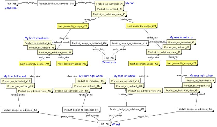
Note that this trivial example only have three Parts (white), the "Volvo S80" car, the "wheel axis" and the "wheel". In a parts assembly, one Next_assembly_usage would have the quantity "2", and the other the quantity "4". In the individual product assembly here, we have seven instances of Product_as_realized (yellow), one for each occurrence and identified uniquely (supposedly), related in an assembly structure by six instances of Next_assembly_usages (bright yellow)..
NOTE The diagram above is very incomplete, all details have been suppressed, such as identifiers, attributes, View_definition_contexts and Product_category.
A Breakdown provides a way to model the structure of a product for views other than part specification. Breakdown is discussed in C004: representing_breakdown_structure and in product_breakdown_for_support. The breakdown concepts apply to Product or Product_as_realized instances. Breakdown_element_usage instances connect instances of Breakdown_element_definition into a tree, same as using their supertypes.
Breakdown enables additional capabilities that are not explicitly provided with the generic design assembly structure:
EXAMPLE An actual product realizes a maintenance breakdown element.
Several specialized breakdowns have been defined in PLCS. Physical_breakdown or Zone_breakdown are often used to break down a product as realized. The Zone_breakdown enables a spatial zone to be identified for each of its elements, and can be used to establish what occurrence of a component, or slot is intended.
For more information on Breakdowns, see C004: representing_breakdown_structure.
A maintenance view may need to contain information about the state of assembly, that is, which components are removed for inspection. The state may need to be tracked over a length of time, perhaps the entire life of each component product of interest (see C041: representing_state_observed).
A Attachment_slot represents the position in which a Part is or can be attached to an assembly and as such can be seen to be an integral part of an assembly. The representation of slots allows the usage history of the Attachment_slot to be recorded, in addition to that of the Part which might occupy it. This can be important where different equipment are used in complex products where the performance of that product might vary according to the equipment fitted.
EXAMPLE The pylon mounting on an aircraft wing is used to carry a radar, or fuel tank. The mounting has an associated slot. The fatigue life of the mounting will be determined differently depending on what is fitted at the slot and the duration of operating in that configuration which could be based on flying hours, landings, the calendar or some other measure.
NOTE However, an assembly need not define any Attachment_slots if undesired. Hence, Attachment_slots are defined within a separate capability.
The detailed description of Attachment_slot representation, it's link to the assembly and identification of the Part or product that occupies the Attachment_slot is presented in capability C086: representing_slots.
Slots may also be defined using Breakdown_elements (see C004: representing_breakdown_structure. For data that is primarily focused on the design, the use of Attachment_slots and Parts combined in an assembly structure using Next_assembly_usages may be preferred. For data that covers early design stages, and/or in-support life cycle stages, breakdowns are probably a better altternative. Both menthods are provided by AP239 for backward compatibility with other models, and for the simple fact that business requirements differ.
The following sections define a set of templates for the capability, where a template is a specification of a set of entities that need to be instantiated to represent a given set of information.
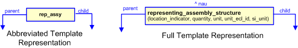
This section specifies the template representing_assembly_structure.
NOTE An explanation of a template and the associated instantiation path is provided in the Template overview section.
This template describes how to represent the relationship between a component and its immediate parent assembly in a product structure, e.g. a parts assembly. As components and assemblies, different instances of Product_view_definition (or subtypes thereof) may be related together. Subtypes of this entity that correspond to entities such as; Part, (e.g. Part_view_definition), Product_as_individual, (e.g. Product_as_individual_view), Attachment_slot, (e.g. Attachment_slot_definition), Interface_specification, (e.g. Interface_specification_definition), and Interface_connection, (e.g. Interface_connector_definition) may therefore, be used.
This template should in particular be used to create the assembly structures that represent traditional Bill of Material structures (i.e. design and manufacturing part structures), as well as simple product structures for real products. For more complex structures, especially when several product structures are used to represent the product across many life cycle stages and domain views, it is probably better to use breakdown structures (see C004: representing_breakdown_structure).
target
is the parameter to which the
Next_assembly_usage
is bound.
| Entity in path | Value | Inherited from |
| Next_assembly_usage.id | '/IGNORE' | View_definition_relationship.id |
| Next_assembly_usage.relation_type | '/IGNORE' | View_definition_relationship.relation_type |
| Next_assembly_usage.description | '/IGNORE' | View_definition_relationship.description |
| Next_assembly_usage.location_indicator | @location_indicator | Assembly_component_relationship.location_indicator |
NOTE this characterization is optional.
The Next_assembly_usage may be classified using external reference data, as described in assigning_reference_data. The class must be a subtype of "Next assembly usage" (urn:plcs:rdl:std:Next assembly usage). Example of classes (not standardized) are manufacturing assembly illustrated parts list
NOTE The assignment of date and time information is described the capability C010: assigning_reference_data.
NOTE this characterization is optional.
A Next_assembly_usage may be given an identifier, using assigning_identification. The identifier shall be classified as "Relationship identification code" (urn:plcs:rdl:std:Relationship identification code) or one of its subclasses, and should have an organization as owner.
NOTE The assignment of identifiers is described the capability C001: assigning_identifiers.
NOTE this characterization is optional.
The Next_assembly_usage may be assigned a date and time, e.g. to indicate when it was created. Such a time-stamp could be used to infer dated effectivity for the assembly structure, but if that is the reason, it is recommended that effectivity shall be used (as described below), instead.
A date and time may be assigned to a Next_assembly_usage using assigning_time. If only the date is desired, the time parameters shall be set to "0".
The date and time shall be classified using a subclass of "Date actual" (urn:plcs:rdl:std:Date actual) or "Date planned" (urn:plcs:rdl:std:Date planned).
NOTE The assignment of dates is described the capability C036: assigning_date_time.
NOTE this characterization is optional.
An effectivity may be assigned to the Next_assembly_usage. This shall be done using entity Effectivity_assignment.
For example, a dated effectivity shall be assigned using template assigning_dated_effectivity.
NOTE The assignment of effectivities is described in capability C006: assigning_effectivity.
NOTE this characterization is optional.
A description of the relationship may be provided using the template assigning_descriptor. This shall be applied to the ^next_assembly_usage reference parameter. The following template call shows how this shall be instantiated.
NOTE The assignment of description information is described the capability C095: assigning_descriptor.
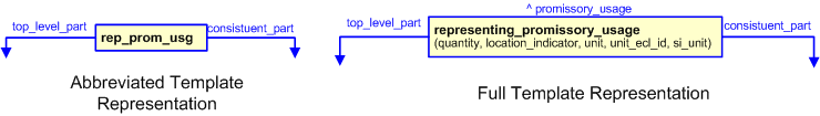
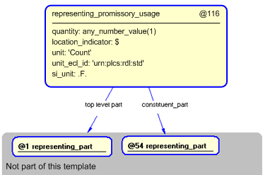
This section specifies the template representing_promissory_usage.
NOTE An explanation of a template and the associated instantiation path is provided in the Template overview section.
This template describes how to represent a promissory usage relationship between components and some higher-level assembly that is not the immediate parent in the hierarchy. This template is specifically targeted at Part_view_definition(s) that occur within the design stage of an assembly structure. From a usage context, it may be important to relate an outsourced component to a top-level assembly definition related to a configuration and product concept. A supplier may not need to know the detailed assembly structure in between. The promissory component usage may be useful during early design phases to create preliminary BOMs for prototyping.
target
is the parameter to which the
Promissory_usage
is bound.
| Entity in path | Value | Inherited from |
| Promissory_usage.id | '/IGNORE' | View_definition_relationship.id |
| Promissory_usage.relation_type | '/IGNORE' | View_definition_relationship.relation_type |
| Promissory_usage.description | '/IGNORE' | View_definition_relationship.description |
| Promissory_usage.location_indicator | @location_indicator | Assembly_component_relationship.location_indicator |
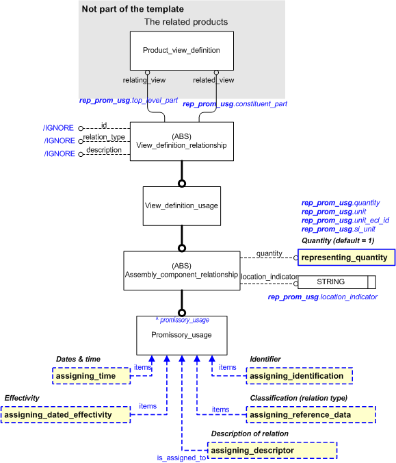
NOTE this characterization is optional.
The Promissory_usage may be assigned a date and time, e.g. to indicate when it was created. Such a time-stamp shall be used to infer dated effectivity for the assembly structure, but if that is the reason, it is recommended that effectivity as described below, shall be used instead.
A date and time is assigned to a Promissory_usage using assigning_time. If only the date is desired, the time parameters shall be set to "0".
The date and time shall be classified using a subclass of "Date actual" (urn:plcs:rdl:std:Date actual) or "Date planned" (urn:plcs:rdl:std:Date planned).
NOTE The assignment of date and time information is described the capability C036: assigning_date_time.
NOTE this characterization is optional.
An effectivity may be assigned to the Promissory_usage. This shall be done using entity Effectivity_assignment.
For example, a dated effectivity is assigned using template assigning_dated_effectivity.
NOTE The assignment of effectivities are described in capability C006: assigning_effectivity.
NOTE this characterization is optional.
A description of the relationship may be provided using the template assigning_descriptor. This shall be applied to the ^promissory_usage reference parameter. The following template call shows how this shall be instantiated.
NOTE The assignment of description information is described the capability C095: assigning_descriptor.
NOTE this characterization is optional.
An identification of the relationship may be provided using the template assigning_identification. This shall be applied to the ^promissory_usage reference parameter. The following template call shows how this shall be instantiated.
NOTE The assignment of date and time information is described the capability C001: assigning_identifiers.
NOTE this characterization is optional.
The Promissory_usage may be classified by using the template assigning_reference_data. This shall be applied to the ^promissory_usage reference parameter.
NOTE The assignment of date and time information is described the capability C010: assigning_reference_data.
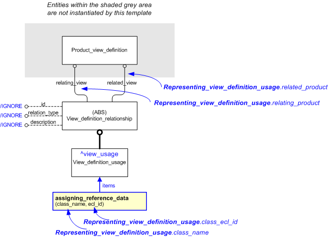
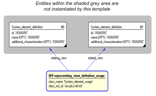
This section specifies the template representing_view_definition_usage.
NOTE An explanation of a template and the associated instantiation path is provided in the Template overview section.
This template describes how to represent a relationship between two Product_view_definitions, where it is considered that the related product is used in the context of the relating product.
target
is the parameter to which the
View_definition_usage
is bound.
| Entity in path | Value | Inherited from |
| View_definition_usage.id | '/IGNORE' | View_definition_relationship.id |
| View_definition_usage.relation_type | '/IGNORE' | View_definition_relationship.relation_type |
| View_definition_usage.description | '/IGNORE' | View_definition_relationship.description |
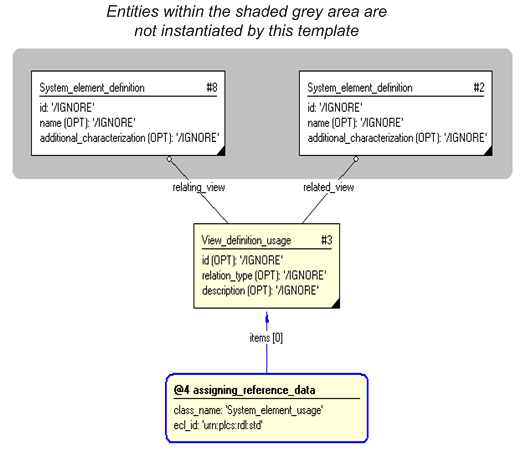
          #2 = SYSTEM_ELEMENT_DEFINITION('/IGNORE','/IGNORE','/IGNORE',$,(),$);
          #3 = VIEW_DEFINITION_USAGE('/IGNORE','/IGNORE','/IGNORE',#8,#2);
          #5 = CLASSIFICATION_ASSIGNMENT(#6,(#3),'/IGNORE');
          #6 = EXTERNAL_CLASS('/NULL','System_element_usage','/IGNORE',#7);
          #7 = EXTERNAL_CLASS_LIBRARY('urn:plcs:rdl:std','/IGNORE');
          #8 = SYSTEM_ELEMENT_DEFINITION('/IGNORE','/IGNORE','/IGNORE',$,(),$);
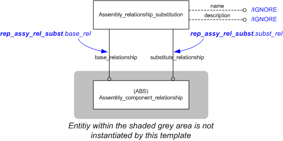
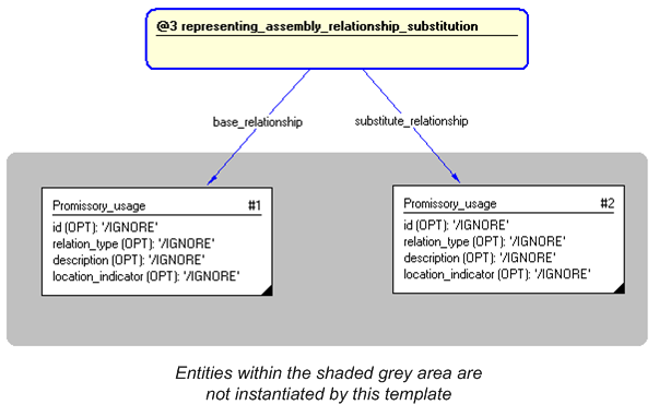
This section specifies the template representing_assembly_relationship_substitution.
NOTE An explanation of a template and the associated instantiation path is provided in the Template overview section.
This template describes how to represent that a the usage of one Product_version can be substituted by the usage of another Product_version in a specific assembly structure.
NOTE Both assembly relationships shall refer to the same Product_view_definition of the same assembly.
NOTE An Assembly_relationship_substitution defines a one-way substitution, i.e. if 'A' is specified as a substitute for 'B', 'B' is not implied to be a substitute for 'A'.
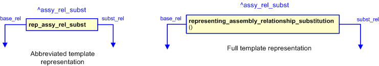
target
is the parameter to which the
Assembly_relationship_substitution
is bound.
| Entity in path | Value | Inherited from |
| Assembly_relationship_substitution.name | '/IGNORE' | — |
| Assembly_relationship_substitution.description | '/IGNORE' | — |
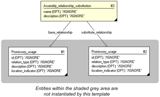
The instance model in STEP XML exchange file format (ISO 10303 Part 28 ed.2 syntax) is:#1 = PROMISSORY_USAGE('/IGNORE','/IGNORE','/IGNORE',$,$,$,'/IGNORE'); #2 = PROMISSORY_USAGE('/IGNORE','/IGNORE','/IGNORE',$,$,$,'/IGNORE'); #3 = ASSEMBLY_RELATIONSHIP_SUBSTITUTION('/IGNORE','/IGNORE',#1,#2);
This capability "Representing an Assembly Structure" is related to the following capabilities:
This capability "Representing an Assembly Structure" is dependent on the following capabilities:
The following classes of reference data are required for this capability:
© OASIS 2010 — All rights reserved